Hello, this is my first post on your fine forum. I am pretty much a total newbie as far as building my own amps, so excuse my ignorance in advance. I am currently building a 12 watt solid state amp from a book designed by Randy Slone. I have built the amp as according to the schematic (or so I think I did) and am using a 24 V 2 amp transformer with rectifier and 1000uF smoothing capacitor. The loudspeaker I'm using is a 4 ohm car speaker. When I plug in the circuit there is static with a pulsing noise in the background, this is with no input source. Once I plug in a source, all I can hear is a horrible noise, that I can only describe as clipping, as best I can tell it is clipping at about a 1 Hz period. There is no audible music. I have swapped out all the transistors, in case there was a bad part. This had no effect. I checked all of the resistors, and some were a bit off, but within their specified tolerance. I don't know what to look for here, and would appreciate any advice. Thanks in advance.
Attachments
48VA (24Vac & 2Aac) is a very small transformer for a power amplifier.
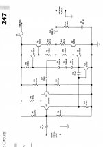
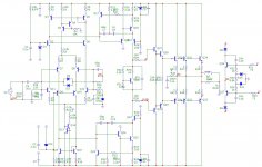
The pic shows an AC coupled single supply push pull amplifier.
The bias to the input transistor is provided by the pair of 22k resistors and the 10uF allows deep bass to be passed through. All acceptable so far.
Now look at the currents through the LTP.
If 600mVbe is across the VAS transistor then that defines the LTP current in the left (+IN) half of the LTP.
The 56k defines the total tail current through the LTP.
What is the current through the -IN half of the LTP? Big problem !!!!
The VAS bias current is defined by the 5k6. This appears to be ~3.2mA. The bias voltage diodes will develop ~2000mV when passing ~3mA. This bias voltage will not turn on the output stage to an optimally biased ClassAB stage.
The bias voltage is not shown as thermally compensated. For ClassB this might be OK if the heatsink is large enough. For ClassAB it is simply wrong.
I may be speaking out of turn, but this seems to be typical of quite a few (many) Slone schematics. Is this presented as a design exercise or as a proposal for a fully developed working amplifier?
To All,
am I reading this schematic correctly?
Last edited:
I don't see a problem with this schematic, R1 and R2 bias Q1, while Q2 is biased by R5 and R6. Any voltage mismatch is corrected by R7, which has a DC coupling to the output, so the output will settle so that everything is in equilibrium. Together with R5 and R6 (which are in parallel for AC when viewed from the base of Q2), R7 forms a voltage divider which sets the gain to about 10x. I agree that in this case, Q1 and Q2 will not carry equal idle currents, but since DC offset is no issue here (DC blocking cap on the output), who cares?
You can say a couple of things of this schematic that would make it a better amp, but that's not the point here. It should work as is, and for mikedrz, it doesn't. Mike, could you post a picture of your built amp? It sounds like the thing is oscillating. Are there any components getting hot to the touch? How are the capacitors connected?
The size of your transformer is of no concern for now. Although it may be desirable to have a somewhat larger transformer if you intend to keep on using it continuously with a 4 Ohms load (for 8 ohms it should be just fine), don't worry about it during testing.
@AndrewT: it seems to me like this is a design exercise, because I am missing a few things, most notably decoupling and thermal coupling between the biasing diodes of the output stage. But it should work nevertheless, although I wouldn't expect too much from it in terms of quality. It is a class B amp, no doubt about that, and the low bias will indeed prevent it from running away.
Last edited:
This is a project with a full parts list, and even plans for a PCB. However I have heard people on other forums mention that there may be a problem with the coupling, and an effecting reffered to as "motorboating" haha. The diodes are supposed to be connected to the heatsink of the output transistors.
It looks like a circuit from a magazine article in the early 1970's, before people had learnt how to get the best out of the standard architecture. May be OK as a cheap PA amp, but don't expect to get much music out of it.
As the circuit has no supply decoupling it will be critically dependent on the quality of the PSU. My guess is that 1000uF is a bit too small as a reservoir cap.
Checks: increase the value of R7 (to temporarily reduce feedback), then check DC voltages. See if it works in this state (but it will have greater gain). Report back.
Aren't you being a bit harsh on Slone?
Motorboating is something that occurs in AC coupled amps with the + and - inputs reversed, or with decoupling gone wrong. Did you use the PCB layout by Slone? Try connecting the PSU buffer cap as close to the board connections as possible. If you use your own layout, it could be anything, so post a picture if you can!
Motorboating is something that occurs in AC coupled amps with the + and - inputs reversed, or with decoupling gone wrong. Did you use the PCB layout by Slone? Try connecting the PSU buffer cap as close to the board connections as possible. If you use your own layout, it could be anything, so post a picture if you can!
I've constructed the circuit on a breadboard and it looks kind of messy and would not photograph well. However I have gone through all the connections with a fine tooth comb. This circuit was meant to be a simple one with inexpensive parts and a simple power supply. The transformer is 24 V peak to peak, which translates to about 38 V DC after it is rectified. He breaks down each section of the amplifier before he leads to the final circuit aswell. He explains the theory behind it aswell, but it is a little over my head at this point.
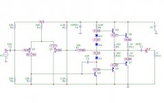
This amp will work, but a couple of component changes may make it work better. THD is around 1%, it is stable (no oscillation) phase margin is around 100 degrees. Here is a simulation showing node voltages using a 34VDC supply. Go see if your voltages are close to these.
Attachments
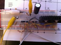
I have attached a pic of my sloppy circuit for whatever it's worth. Thanks for all of the replies everyone, you folks are great and well resourced. I was measuring the voltages at idle and a diode shorted out to the speaker output and something went up in smoke. However before that happened, I was able to verify that the voltages were around 18 volts at the transistor base and emitter, they were exactly the same, which was different from the simulation. One other thing I have noticed before I broke the damn thing even more was; that when I unplugged the transformer from mains, it stops oscillating and faintly played music for 2 seconds. This was probably from the charge in the caps. I wanted to reuse the parts after breadboarding and that's why I didn't want to trim the leads. I guess I'll have to start over again at any rate. I have measured the voltage coming off the power supply and the ripple seems pretty small, the book called for a 1000uf cap; but I guess I could try a bigger cap. I'll have to play around with it some more until either I lose my patience or run out of parts. haha I will keep everyone posted, and thanks again for everybody's help.
Attachments
Last edited:
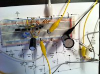
Success!! I was able to get it done with everybody's suggestions, I was down to my last power transistors and had to rebuild from scratch. I used the 4700uF@50V cap placed directly on the breadboard. I have forgone the heatsinks just for testing purposes and realize that I would have to put those back on. It doesn't sound all that great, however it's important that I got this done!
Now I have an MJ15003, and MJ15004 waiting for my next amp project . I don't feel like frying those just yet; so I will save those for another day.
Thanks again, great forum!
Now I have an MJ15003, and MJ15004 waiting for my next amp project
. I don't feel like frying those just yet; so I will save those for another day.Thanks again, great forum!
Attachments
I had reached that conclusion while he was alive and stated so on this Forum.Aren't you being a bit harsh on Slone?
I have not seen any evidence that would change my opinion after he has passed away.
Building things like that cob-web could make you uncle Charlie's next best friend.
Andrew, Hitler is assumed dead but many still hates his guts, so there, could apply to anyone.
There are evidence, I assure you, and I have landed the boring job to try and rectify it and make some of his designs actually work, which is extremely finicky.
I am almost sure this simple amp shown in this thread is not from him (unless a very early attempt) as he had the tendency to chuck a whole bucket full of components into it, some for no good reason at all, just so it would look complex. So I would support your opinion.
Who's uncle Charlie? Haha This is out of a book he wrote about basic intro to electronics. The first 7 chapters teach you electronics theory, and near the end he has two amps as projects. The main project in this book is a dual voltage adjustable power supply. This book isnt one his amp cookbooks where he probably gets fancy. A lot of the parts he calls for are either obsolete or really queer values that are hard to find.
Update
Here is an update if anyone is interested, I've built the PCB version of this amp. I have also built the "lab quality dual power supply" that was from the same book. This power supply is rated at -36 and +36 VDC. I measured the Voltage ripple at 80 mV p-p @ 36 V through a 10K resistor as a load. When I'm using this power supply I get the motorboat effect again, however I borrowed a friends professional power supply, that only goes to 30 VDC and the amp works with this power supply, but still motorboats a little on start up.
All in all, this design seems to be a piece, and I don't know if I should bother with his 50 Watts RMS "professional grade amplifier" that is based on the MJ15003 and MJ15004 Power transistors. Both these amps are mono for some reason.
Last edited:
- Status
- This old topic is closed. If you want to reopen this topic, contact a moderator using the "Report Post" button.
- Home
- Amplifiers
- Solid State
- 12 Watt amp, guidance required