I just ebay'd one to check it out, but it will likely come in after Xmas. If it strips down well, and the output can be rectified and filtered without causing the regulator to hiccup or hang during turn-on then it should be a convenient little unit. It will be interesting to see what circuit is inside. I was half-way through preparing a non-isolated flyback for a 'few' watt amp, but this may be a whole lot easier ")
Payloadde, I like the 12ax7a preamp power supply diagram. It looks very similar to the one I put together. The first one I tried used a 555 timer with a voltage adjust. The adjust went back to the control pin. It actually makes it change frequency to keep it in check. As for the others I have a broken cigarette lighter power supply like the one on ebay so can just take a look at it and see if it is workable. I did look at it before not sure why I didn't go farther with it. My brain is not as spry as it used to be so sometimes I don't want to take the time to think it out. even though that is the fun of it.
I am impressed by the 20 watt power supply Funker built. Also,The UC3843 looks very useable and is everywhere on the net. If you click on the image tab at the top of your browser, diagrams galore pop up. I think I would like to run my supply at 50KHz - 100 KHz rather than anything lower. I wish I had more time on my hands. I need to win the lotto. I wouldn't care about taking trips, heck I would build stuff all day, put me a cot in the shop for naps. I hope I have time tomorrow to try something with what I have. still getting an urge to buy one of those little inverters from ebay. Going to wait and see what I can do with the one I have now. Sure am thankful for all the replies I have received. Once I build something I will come back and show you what it is. I've got more junk around here, so doesn't make sense for me to buy more. That's about how it goes. You save for years all the stuff for what? so you can go out and buy what you needed in the first place. I am almost to the point of cleaning house and just keeping a few good items and just buy what I need from now on. Doesn't make sense to have a bunch of parts you cant find anyway. Oh well Time to sleep on it, will try tomorrow to build something.
I am impressed by the 20 watt power supply Funker built. Also,The UC3843 looks very useable and is everywhere on the net. If you click on the image tab at the top of your browser, diagrams galore pop up. I think I would like to run my supply at 50KHz - 100 KHz rather than anything lower. I wish I had more time on my hands. I need to win the lotto. I wouldn't care about taking trips, heck I would build stuff all day, put me a cot in the shop for naps. I hope I have time tomorrow to try something with what I have. still getting an urge to buy one of those little inverters from ebay. Going to wait and see what I can do with the one I have now. Sure am thankful for all the replies I have received. Once I build something I will come back and show you what it is. I've got more junk around here, so doesn't make sense for me to buy more. That's about how it goes. You save for years all the stuff for what? so you can go out and buy what you needed in the first place. I am almost to the point of cleaning house and just keeping a few good items and just buy what I need from now on. Doesn't make sense to have a bunch of parts you cant find anyway. Oh well Time to sleep on it, will try tomorrow to build something.
Payloadde, ... The first one I tried used a 555 timer with a voltage adjust. The adjust went back to the control pin. It actually makes it change frequency to keep it in check...
If done correctly, the adjust via the 555 control pin alters the pulse width and not the frequency.
Doubt it, much cheaper now to add electronics than to use iron.Which type of circuit configuration did you think is being used? They may just have a small 50/60Hz transformer, although the size is pretty small.
If done correctly, the adjust via the 555 control pin alters the pulse width and not the frequency.
Not in the circuit shown (and not in the standard 555 circuit, where duty and frequency are both modulated in a nonlinear fashion), where on-time is approximately constant (due to the peak current mode feedback) and threshold voltage is varied, the threshold being compared to an RC time constant.
This isn't bad in and of itself either; as long as frequency can drop arbitrarily low, the very low duty cycle can allow high efficiency under light loads (although the high current consumption of the NE555 won't win you any awards). Many of my blocking oscillator designs exhibit this behavior. The downside is increased ripple due to the low frequency and hysteretic regulation behavior.
Tim
Doubt it, much cheaper now to add electronics than to use iron.
I expect the same. Let's see when arriveth...
Printer2 - I agree - but somewhat doubtful - it will be interesting - can't wait till Xmas
I have been collecting used transformer based wall warts of various voltages. They are getting harder to find, bow most equipment is coming with switching power supplies. More capacity, better regulation, wide range of input voltage. Considering they would have to switch the dc anyway (it is for a car if you missed it) I would think it would be a high frequency switching circuit.
whoa, getting a bit technical.I didn't measure the frequency from the 555 when it did it's changing just assumed it changed frequency as I could hear the tone of it as it worked, when I was tweeking on the hv adjust. Good news is I looked at the 80 watt cigarette plug type power source, the one I have that doesn't work, and it does have a TL 494 chip on a small board that is soldered to the main board. man that thing is small. I used to be able to read the numbers on IC's, now I can barely see it with glasses on. So I am going to see if the TL 494 still functions ok and use that chip. See what frequency it is running at and go from there. I don't have anything spectacular for frequency meters other than a homemade job that uses a preprogrammed chip and a display. Actually works ok. Not sure of accuracy but precision is not needed for this. I think it cost me about $15- $20 to build. Have to fix my oscopes all of them quit working. Tired of fixing things so I can make stuff. Takes time away from the fun things to do. I cant afford to go out and buy what I need so I have to make do with what I have. I think everything I have is junk, but it's all I have. So even though some things are not very expensive, I still have to do it the hard way. $5 here, $ there adds up. Then if those items don't work out then I am out of $5. Back in my drinking days that would be enough to get all liquored up, rot gut stuff of course. Let you how the TL 494 works out. Let me know how the $5 power plug from ebay works out for you.
Last edited:
have concluded there are 2 chips TL 494 on my 80 watt cigarette power supply. I don't know, but I cant hardly see that small anymore. I might have to stick with a 555 timer ic. I did remove the board that holds the two chips. I cant see the traces as they are covered with some kind of enamel coating, so pretty much worthless for me, unless I remove the chips and start over with a fresh board to mount them on.
I do want to mention I came across a program that calculates the values needed for a few different styles of inverters. doesn't show anything but the the design placement of the coils and power transistor or mosfet for that type of circuit and gives you values based on what you put in the formula windows. and gives ripple and power input-output values. I will have to upload to my website I guess for all to download and use. It has boost circuit, and a couple others, septic, and about 4 or 5 more. I did try a boost circuit since last post. It worked then it shut down. Cant figure out why it works one time and not the next. A little buggy in my design. I am going to have to start over from scratch again as my first board I use for experimenting does not have a plug in socket for the 555 and I want to make it easier to experiment with. I just remembered I came up with a design a few years ago that worked great for my hydrogen project. I will change a few values and use it as a boost circuit. That design is on a website I started and never finished. I am now going to have to fix the website so it is easier to find stuff on it. Sorry I cant do it now. let me give you the link to the diagram. I will have to come back in a day or so with the program I mentioned and put it on there too. here is the link to my original diagram HHO- PWM
So when I get a moment or two I will try it again using a 555 timer ic in a boost circuit design. According to the program it has less ripple than a transformer design.
It's sad, but folks it actually has taken me three years just to start playing with electronics again. I used to eat and sleep electronics. made a few pirate tube radio transmitters for fun back in the day, so I could play music and pretend I was a DJ... ha-ha.
Last edited:
Well it arriveth. No time to play but I had to see if it works. Quick test no load with 12.3V. 167VI expect the same. Let's see when arriveth...
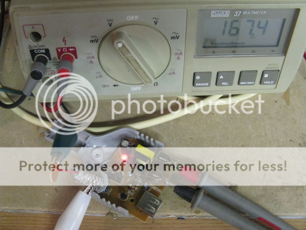
Well it arriveth. No time to play but I had to see if it works. Quick test no load with 12.3V. 167V
What is the frequency, with such tiny transformer?
Sorry, doing renovations on the kitchen, no time to play, well just a little.
With a 47k load at 12v the output drops down to 164V. With a 10k load drops down to 155V.
At 13.5V with no load 168V, with 47k load it drops down to 165V. With 10k load drops down to 160V. Would have to check the actual voltage with a scope, not sure if the meter is really reading. Either way I am happy enough for $5.00.
OT
omg - it was worth looking just to read the chinglish... My fav is "iron-heart transformers". Sounds like a good business name come to think of it.
/OT
omg - it was worth looking just to read the chinglish... My fav is "iron-heart transformers". Sounds like a good business name come to think of it.
/OT
- Status
- This old topic is closed. If you want to reopen this topic, contact a moderator using the "Report Post" button.
- Home
- Amplifiers
- Tubes / Valves
- 12 volt to 300 volt inverter question for tubes