My Xmas pressy took a little longer - no bench testing for a few days - but did a quick schem.
http://dalmura.com.au/projects/Car charging converter.pdf
http://dalmura.com.au/projects/Car charging converter.pdf
Hi Trobbins, that link doesn't seem to work 
My amp got completed last night.
Butchered 230 volt inverter, providing +320 V HT , and -48VDC for bias.
Other than the PSU, the amp section is very much modeled on Triode Dick's Mono Bill, except for the ECC99 phase splitter is tweaked to take a 6N6P and there's another 6N6P as a pre-amp (with LED bias) http://www.triodedick.com/monobill/monobill schema versterker.GIF
With the lower HT I'm not getting the output power, but it sounds great, even with Hammond Iron.
The 15 volts for the phase splitter is derived from a small DC-DC converter module.
Now to see if it's reliable. The tubes are all supported on rubber grommet mounts, to give *some* shock abosorption (think CD player here!)
The hyperlink doesn't like spaces - you have to copy and paste the whole text :-(
I'll use the correct html this time
http://dalmura.com.au/projects/Car charging converter.pdf
Ciao, Tim
I'll use the correct html this time
http://dalmura.com.au/projects/Car charging converter.pdf
Ciao, Tim
It's just a DC output, which is great. With 160-200V available at 3'ish watt, then it will go well with an abandoned 12VDC switchmode plugpack. A few well placed surface mount ceramics, and perhaps input electrolytic and smt inductor should make it innocuous. And it'll have that authentic valve rectifier sag for sure with an output stage!
A quick look on the bench indicates it's a nice little dc/dc. I was getting 175V unloaded with 12V in as well. The default 7.5V zener sets the nominal output voltage - increasing to 10V zener gave 240V unloaded at 12V.
Light loading pushes switching frequency above 100kHz, falling to nominal 50kHz at 2W load. Output voltage droops, with a nominal constant power type characteristic as per a flyback. The parts run cool at 2.5W output, and should still have good safety margin at 15V input.
I'm going to put mine in a simple 6EB8 PP for guitar use. I'll cut the 0V trace and put the output dc on top of the 12V input to give me a negative 12V supply for fixed bias, and the 12V for series heaters.
The pcb nicely allows smt ceramics to closely bypass the switching loops - the hv loop was particularly poor to the 2u2 electro. Theres also holes for an input electrolytic.
finally got it piece of cake now!
After some frustration I finally succeeded in getting some nice voltage with a small transformer at that. Not sure why sometimes things don't work like you think they ought to. I have been using a 555 timer and according to my homemade freq counter is running from about 250 Hz to 330 Hz or so in my final design. I tried running the 555 into a 741 driver, transistors and combinations to drive a mosfet. The result was I could never get over 40 volts or so no matter what I did except for when I used the feedback circuit from the diagram where the 555 timer gets feedback voltage from the output and goes to pin 5 of the 555. I always had heating on the mosfet and even the transformer. Now I dont have any heat on the mosfet and very little if noticeable on the transformer. The output is 200-300 volts DC. It can go as high as 800 volts if you let it but then heating starts to occur. The secret of the whole thing was in the output side of the transformer and a couple other things I did to make it run cool. first off the output does not go into a regular half wave rectifier, it will not work and you will hover at 40 volts or less. Something is fighting something there not sure what. as soon as I changed the circuit to a tripler design, man did it work. You must come off the transformer with a cap in series in order to solve the problem of low voltage. Cmon if I measured 40 volts then I use a tripler and now its 600 volts doesn't make sense unless I truly had more voltage to begin with and it was being killed. I can upload a diagram later, but what I have is a 220 meg in series with a 470 ohm resistor to ground on the output for my feedback. At the junction of the 220 meg and 470 ohm resistor i have a 10k pot which is across the 470 ohm resistor. Now that I think of it I might need to change that. anyhow the center goes to pin 5 of the 555 timer directly. Now between the B+ and the transformer is a 10 ohm sandbox type resistor that feeds into an LM7805T regulator (weird I know) then to the transformer. The ground leg goes to a trimpot set right at about 400 ohms. what you do is adjust the trimpot for maximum voltage which might not necessarily be at one end of the pot. Then you adjust the feedback pot for the voltage that you want. I also have a 100k resistor across my output as a load test. It will get it hot. I am using a 4.7k resistor from pin 7 to 6 another 4.7k resistor from 8-7. the timing cap is a .1 uf. I found that if you fine tune the frequency, I suppose to match the transformer you are using it will not heat nor will the mosfet but the 100k resistor will smoke. it was a half watt resistor. I am sure I have plenty to run my 12ax7a tube now and then some. If I need more I can change out the transformer. It would go nuts without the lm7805 regulator and start on a course of burnout. as the voltage would kick up to about 800 volts then parts would get hot and it would keep changing erratically. this seems to be stable now and holding with the parts I have installed. I can do without the lm7805 and just the resistor, but somehow it is preventing the transformer from overheating and I still get the same output, so it seems. Now I have to put it all together now and hook up the tube and see how it does. Oh I am using 22uf/450volt caps and 1n4007 rectifiers. I wonder if a different choice of caps would be better, but I have to use what I have available at home. Oh if you hook up the 555 with a transisor at pin 5 like one the diagrams show and feedback to that, your mosfet will get hot. Only by hooking up the pot directly to pin 5 as stated here, it will it not get hot. So whatever it does at pin 5 must have something to do with the output waveform in such a way the mosfet likes it and runs cool. I mean cool to the touch no heatsink. it is a f101e mosfet if that helps. maybe its a f1010e, i am not in front of my work at the moment. Yeah I ruined a good cheap meter on this one. when i had the 40 volts i disconnected the rectifier to check the voltage AC and there was one hell of a spark and wild bluish glow when the two transformer leads almost touched. That is when I knew I had more than 40 volts. So I attempted to hook up the meter to check the Ac fr4om the transformer to prove my theory and the same bluish glow was inside my meter now at the lead plug ins. Even though set to 1000 volt scale. toasted it good. anyhow that is how I came to design the rest of the circuit after that incident. So if any of you are having trouble getting a good output, just hook up an electrolytic cap in series with the output side of the transformer and rectifiers after that. Even a doubler would be choice idea. That is what had me stopped all this time was my output circuit. Like i said wont work with a rectifier and then a cap, at least not my trials and errors on this one. Ok I drew a quick diagram excuse the mess. I will make it better later.
After some frustration I finally succeeded in getting some nice voltage with a small transformer at that. Not sure why sometimes things don't work like you think they ought to. I have been using a 555 timer and according to my homemade freq counter is running from about 250 Hz to 330 Hz or so in my final design. I tried running the 555 into a 741 driver, transistors and combinations to drive a mosfet. The result was I could never get over 40 volts or so no matter what I did except for when I used the feedback circuit from the diagram where the 555 timer gets feedback voltage from the output and goes to pin 5 of the 555. I always had heating on the mosfet and even the transformer. Now I dont have any heat on the mosfet and very little if noticeable on the transformer. The output is 200-300 volts DC. It can go as high as 800 volts if you let it but then heating starts to occur. The secret of the whole thing was in the output side of the transformer and a couple other things I did to make it run cool. first off the output does not go into a regular half wave rectifier, it will not work and you will hover at 40 volts or less. Something is fighting something there not sure what. as soon as I changed the circuit to a tripler design, man did it work. You must come off the transformer with a cap in series in order to solve the problem of low voltage. Cmon if I measured 40 volts then I use a tripler and now its 600 volts doesn't make sense unless I truly had more voltage to begin with and it was being killed. I can upload a diagram later, but what I have is a 220 meg in series with a 470 ohm resistor to ground on the output for my feedback. At the junction of the 220 meg and 470 ohm resistor i have a 10k pot which is across the 470 ohm resistor. Now that I think of it I might need to change that. anyhow the center goes to pin 5 of the 555 timer directly. Now between the B+ and the transformer is a 10 ohm sandbox type resistor that feeds into an LM7805T regulator (weird I know) then to the transformer. The ground leg goes to a trimpot set right at about 400 ohms. what you do is adjust the trimpot for maximum voltage which might not necessarily be at one end of the pot. Then you adjust the feedback pot for the voltage that you want. I also have a 100k resistor across my output as a load test. It will get it hot. I am using a 4.7k resistor from pin 7 to 6 another 4.7k resistor from 8-7. the timing cap is a .1 uf. I found that if you fine tune the frequency, I suppose to match the transformer you are using it will not heat nor will the mosfet but the 100k resistor will smoke. it was a half watt resistor. I am sure I have plenty to run my 12ax7a tube now and then some. If I need more I can change out the transformer. It would go nuts without the lm7805 regulator and start on a course of burnout. as the voltage would kick up to about 800 volts then parts would get hot and it would keep changing erratically. this seems to be stable now and holding with the parts I have installed. I can do without the lm7805 and just the resistor, but somehow it is preventing the transformer from overheating and I still get the same output, so it seems. Now I have to put it all together now and hook up the tube and see how it does. Oh I am using 22uf/450volt caps and 1n4007 rectifiers. I wonder if a different choice of caps would be better, but I have to use what I have available at home. Oh if you hook up the 555 with a transisor at pin 5 like one the diagrams show and feedback to that, your mosfet will get hot. Only by hooking up the pot directly to pin 5 as stated here, it will it not get hot. So whatever it does at pin 5 must have something to do with the output waveform in such a way the mosfet likes it and runs cool. I mean cool to the touch no heatsink. it is a f101e mosfet if that helps. maybe its a f1010e, i am not in front of my work at the moment. Yeah I ruined a good cheap meter on this one. when i had the 40 volts i disconnected the rectifier to check the voltage AC and there was one hell of a spark and wild bluish glow when the two transformer leads almost touched. That is when I knew I had more than 40 volts. So I attempted to hook up the meter to check the Ac fr4om the transformer to prove my theory and the same bluish glow was inside my meter now at the lead plug ins. Even though set to 1000 volt scale. toasted it good. anyhow that is how I came to design the rest of the circuit after that incident. So if any of you are having trouble getting a good output, just hook up an electrolytic cap in series with the output side of the transformer and rectifiers after that. Even a doubler would be choice idea. That is what had me stopped all this time was my output circuit. Like i said wont work with a rectifier and then a cap, at least not my trials and errors on this one. Ok I drew a quick diagram excuse the mess. I will make it better later.
Attachments
I got an identical looking 150w unit from eBay, 220v version, and it has a "pseudo" AC output, with a "proper" 50KHz smps and an h-bridge. They even managed to cram a tiny fan in there. I'll get a picture up later.
Could you please post a picture of the 150W unit?
Thanks,
Jaz
Answered a thread on another site where someone wanted to make a 1W guitar amp using 12V space charge tubes. Gave my opinion and thought using the 5W inverter and a pair of 6AK6's would give around 1W, could not remember what the inverter would do so looked up this thread to find out.
Then I had a thought, rather than two 6AK6's, run one and put a 6AK5 in series with the 6AK6 heater, bypass a couple of mA around the 6AK5 if needed. I have a 70V line transformer that I took apart and added an air gap, not happy with it for a 6AQ5 but it should do nicely for something like this.
Now the question is, do I really need this?
Love to see your experience incorporating the converter and wall wart... I strung together two 6N8Ps (in parallel) and one 6P3P to run off a 12V wall wart (from an old laptop), which also supplied the DC-DC converter to get the 250V needed for the B+. The noise from the SMPS and the converter was not too bad, there was no hum whatsoever, since the filament supply was DC. Without the power trafo, the amp is much lighter and the chassis can be smaller as well.
Jaz
Jaz
I'm doing the same thing with an EL-84 amp now, but I'm using a 24v universal power brick external to the amp. Inside the amp, heaters are in series for the 24v and a 24v to 220v inverter will be used to give about 300v B+. I'm still a few days from getting the hardware finished so I can install the parts and test. A full write up will happen once I'm done. I really wish I could find a 19v to 220 volt inverter - most laptop power bricks are 19v and would be good for an inexpensive power supply, especially for something like a small guitar or computer amp.
Ebay has small "75W" car inverters that plug in to the cigarette lighter socket. The '220VAC' version has a beaut push-pull 12V to 260VDC switchmode in it, on a neat little 55x52mm pcb. Idle input power is 1.4W, and easy to remove the AC H-bridge.
Link to photos, operation, and schematic sketch.
http://dalmura.com.au/projects/75W%20car%20inverter.pdf
Link to photos, operation, and schematic sketch.
http://dalmura.com.au/projects/75W%20car%20inverter.pdf
Inverter for battery operated tube amps
Hi folks,
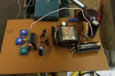
I posted a Circuit in thread #17 the other day. I found some pics I´ve made during the setup. As I said this work in a portable guitar tube amp with EL84 and ECC83. So after all the time the guy who use this amp for street music, he is quite satisfied with its performance . The amp run with a brand new lead acid battery 5 hours.
The iron in this one came from scrapped electronic ballasts. The power Mosfets from motor controllers.
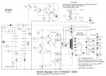
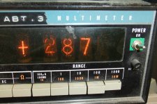
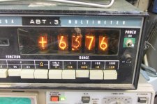
I made another inverter which give an amazing output of 350W from a 12V source. This Inverter shall power up a 2x50 Watter with 4 EL34 for car use.
From left to right:
schematic of the 350W inverter, plate voltage of the 20W inverter, heater voltage of the 20W inverter, setup of the 20W inverter.
73
Wolfgang
Hi folks,
I posted a Circuit in thread #17 the other day. I found some pics I´ve made during the setup. As I said this work in a portable guitar tube amp with EL84 and ECC83. So after all the time the guy who use this amp for street music, he is quite satisfied with its performance . The amp run with a brand new lead acid battery 5 hours.
The iron in this one came from scrapped electronic ballasts. The power Mosfets from motor controllers.
I made another inverter which give an amazing output of 350W from a 12V source. This Inverter shall power up a 2x50 Watter with 4 EL34 for car use.
From left to right:
schematic of the 350W inverter, plate voltage of the 20W inverter, heater voltage of the 20W inverter, setup of the 20W inverter.
73
Wolfgang
Attachments
- Status
- This old topic is closed. If you want to reopen this topic, contact a moderator using the "Report Post" button.
- Home
- Amplifiers
- Tubes / Valves
- 12 volt to 300 volt inverter question for tubes