Hi..
For your comments and suggestions..
All right with this PCB, I am interested in building it ...
Small problem with Apex A9 amplifier construction (solved)
Dear all,
Here is a quick comment concerning a single design in this gigantic thread. I have built two copies of mr. Mile Slavkovic's Apex A9 amplifier, using his own PCB design as published in post # 3570. The amplifier works fine and sounds very nice, but I encountered an initial problem. When the PCB was populated as shown in "APEX A9pcb.pdf", it produced a heavily distorted sound. I measured the voltages across the Z15 zeners in the input stage, and these turned out to be -1.7 and +1.0 Volts! After some head-scratching, I concluded that the values of the series resistors in the power supply lines (3k3 2W) were much too high. The quiescent current of an LM4562 i.c. is 10 to 12 mA, thus, the series resistors should allow 15 to 20 mA to pass to the LM4562 i.c. plus each zener. Since I tested my amp at a PSU voltage of ± 29 Volts, I reduced the value of the series resistors from 3k3 to 820 Ohms, 2 W. After this modification, the amp boards worked perfectly, and I measured 15 Volts (actually, 14.5 Volts, since zeners have some tolerance) across each Z15.
Perhaps mr. Slavkovic can comment? Anyhow, I would like to thank him for a nice project that works well.
Best regards,
arensattic
(aka Aren van Waarde, Groningen, Netherlands)
Are you sure that amplifier can work at +/-29v?Dear all,
Here is a quick comment concerning a single design in this gigantic thread. I have built two copies of mr. Mile Slavkovic's Apex A9 amplifier, using his own PCB design as published in post # 3570. The amplifier works fine and sounds very nice, but I encountered an initial problem. When the PCB was populated as shown in "APEX A9pcb.pdf", it produced a heavily distorted sound. I measured the voltages across the Z15 zeners in the input stage, and these turned out to be -1.7 and +1.0 Volts! After some head-scratching, I concluded that the values of the series resistors in the power supply lines (3k3 2W) were much too high. The quiescent current of an LM4562 i.c. is 10 to 12 mA, thus, the series resistors should allow 15 to 20 mA to pass to the LM4562 i.c. plus each zener. Since I tested my amp at a PSU voltage of ± 29 Volts, I reduced the value of the series resistors from 3k3 to 820 Ohms, 2 W. After this modification, the amp boards worked perfectly, and I measured 15 Volts (actually, 14.5 Volts, since zeners have some tolerance) across each Z15.
Perhaps mr. Slavkovic can comment? Anyhow, I would like to thank him for a nice project that works well.
Best regards,
arensattic
(aka Aren van Waarde, Groningen, Netherlands)
Apex A9 PSU voltage
Hi Thimios,
For the Apex A9 amplifier, a PSU voltage of ± 40 V is the recommended MAXIMUM and ± 35 V is recommended for normal operation. Even at ± 40 V, the 3k3 series resistors will allow to pass only (40-15)/3300 = 7.6 mA. This is not sufficient to feed both an LM4562 and a Z15 zener (10 mA should go to the LM4562 and a few mA should go to the Z15).
In my experience, the A9 works fine at ± 29V. Thus far, I have only tested it on the workbench. In my final build, I will raise the PSU voltage to ± 35V.
Aren
I need a favor, can someone generate pdf for thermal transfer of these two PCBs.
Grateful
Here you go
Attachments
Last edited:
Here you go
Thank you very much Terry !!!
@Prasi, any idea if we need to put the aluminium strip with screws on the GBJ3510 bridge rectifiers on the Compact CRC psu boards for heat dissipation if we are going to use a transformer rated 30 to 35v secondary with 5A to 8.5A current on each secondary with a total 300-600VA?
Thanks
Thanks
Yes, it would especially if operating at higher loads continuously.
For home listening at normal level you can get by without the sink.
If you have a simple infrared thermometer gun, monitor the temperature, if it goes beyond 70 deg at normal levels, best to sink it.
simple solution is take a plain 30mm wide , 1 mm thick Al sheet of 80-100 mm and bend it around a plywood similar to following
Blocked
You can even drill some small holes on the top for heat dissipation.
Hope you got the idea.
regards
prasi
AX14 Golosa
Hello friends, I made an "AX-14 Golosa" with two pairs of output transistors, but, I don't know why it doesn't work properly. The only replacement I made was on the output transistors that I put a pair of 2SA1693 AND 2SC4466 instead of the 2SA1943 and 2SC5200, and in the bias I replaced the BD139 with MJE340. I can't adjust the bias and at the exit I have a noise similar to a siren. My current source provides + -25VDC. I wanted to know if the cause is MJE340 from bias or if there is something else I missed.
Thanks.
Ok thanks Prasi much appreciated.
Remember, at 4 ohm loads at full power (and with pure sine waves), your rectifier may dissipate as high as 8-9 W of power.
=1.2V*7Amps.
But rarely is the case with music and also rail due to sag, dissipation will be lower.
Remember, at 4 ohm loads at full power (and with pure sine waves), your rectifier may dissipate as high as 8-9 W of power.
=1.2V*7Amps.
But rarely is the case with music and also rail due to sag, dissipation will be lower.
I do not have any 4 ohm speaker so I should be fine and also I don't listen at high volumes. I use the audio nirvana 8" full rangers which are like 96db sensitive 8 ohms nominal.
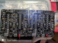
I'm really sad that I can't order PCB from JLCPB but a friend I send the gerbers to him and he is putting together the Apex P30 and Apex Class A PSU layout I did a few months ago looks great I hope all goes well on his build
Attachments
I do not have any 4 ohm speaker so I should be fine and also I don't listen at high volumes. I use the audio nirvana 8" full rangers which are like 96db sensitive 8 ohms nominal.
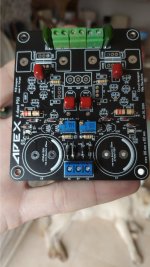
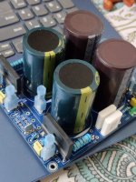
here is how i built mine.
caps are 10000uf, 63V. will be using it for Apex fx-8 bimo mod amplifier.
Attachments
Looking good Prasi, did you calculate the snubber values of RS,CS,RS',CS' for your transformer or can we use generic values here? On your schematic doc I think you said if you do not know the snubber values do not populate but is it possible to put these values without a Quasimodo jig and all.
thanks
thanks
Thanks manniraj,
snubbers are just some arbitrary values of 150R, 150nf, 10nf for rs, cs and cx.
i will use the jig later to find appropriate values, i have quasimodo jig supplied by a kind member.
Well, regarding psu, everything fits and works , i get +/-34.5V from 25V transformer with dual 5 amp secondaries(total 250VA) .
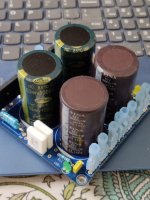
since there are no thermal reliefs (purposely), soldering is a two step process with a 60W iron. First heat the joint with little solder then wait for 2-3 sec and then start feeding the wire.
snubbers are just some arbitrary values of 150R, 150nf, 10nf for rs, cs and cx.
i will use the jig later to find appropriate values, i have quasimodo jig supplied by a kind member.
Well, regarding psu, everything fits and works , i get +/-34.5V from 25V transformer with dual 5 amp secondaries(total 250VA) .
since there are no thermal reliefs (purposely), soldering is a two step process with a 60W iron. First heat the joint with little solder then wait for 2-3 sec and then start feeding the wire.
- Home
- Amplifiers
- Solid State
- 100W Ultimate Fidelity Amplifier