Nice design.
Thanks You!
Thanks You!
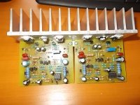
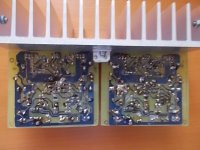
2-pairs AX-14, stereo can be fitted on 196mm x 150mm heatsink 196MM width/150MM length extruded aluminum heat sink.
fan cooling for keeping things cool.
regards
Prasi
Problems with my A9
Hi to All,
Thanks to Mr. Mile for shared so many projects and to Sonal Kunal for PCB.
First I built an A9 channel and tested it. Working from the first start. + 35 0 - 35 V rail, offset 1,4 mV, 30mA biass and perfect sinewave on scop, no oscillation, hum or noise. Nice sound. On out I had 42 Vpp, 42 x 0.707= 29,7 V, 29,7x 29,7/8 = 110 Wrms. It is correct ?
I use my old Sony TA-F261, replace STK 4182 with two A9, PSU and protector.
Rail is + 41.5 0 - 41,5 V cc, transformer has 200 VA. I can't adjust bias, I have 56 mA and 36 mA. When connected the speakers, at one channel both IRF's are distroyed ( drain to source is wire) I use those speakers on Sony TA-F330 and I had no problems.
It is to much rail?? For this rail to be replaces IRf 540/9540 with IRF 240/ 9240 ??
Scuse me my english
Regards
Cornel
Attachments
Hello PrasiHello Rick,
Here you go.
regards
Prasi
A note for those who want to etch their PCBs.
I have made the pdf's such a way that on a 4" x 6" copper clad, one can etch 4 PCBs at a time... Saves copper clad and etchant too...
But I would suggest to make use of cheap board houses, that way one could get double sided PCBs with gnd layer on top
Do you have diy pdf's file in mirror for these one please
Hello Prasi
Do you have diy pdf's file in mirror for these one please
Hello mantrieSolder,
here you go. Is this what you were looking for?
regards
Prasi
Attachments
This thread is a potpourri of many amplifier designs that can easily confuse anyone. So better start at the beginning and all the best.I reckon I might give this a crack. Just got to work out where I start. Looks like many adjustments and tinkering by knowledgeable helpful members.
Xrk971 has made an index thread out of aPex designs, please locate it.
Edit here it Is A Directory of Apex Audio Amplifiers
Last edited:
This thread is a potpourri of many amplifier designs that can easily confuse anyone. So better start at the beginning and all the best.
Xrk971 has made an index thread out of aPex designs, please locate it.
Edit here it Is A Directory of Apex Audio Amplifiers
Hi,
I will search in thread a solution. Thanks for help to prasi and Maverick2020
Regards
Cornel
Hi,
I will search in thread a solution. Thanks for help to prasi and Maverick2020
Regards
Cornel
Hi Cornel,
Although I couldn't locate sch, from layout posted here
100W Ultimate Fidelity Amplifier
and here
100W Ultimate Fidelity Amplifier
I think 42V might be too high for BD139 and BC550/560.
and from the second layout, it is evident that you can use IRFP240/9240
sorry i am not able to help you further, may be olaf or apex will shed more light?
regards
Prasi
I will try soon...
Hello Willy,
Nice!. I dont see 100nF cap across pin 4 /gnd and pin 8 /gnd. Is it smd located on bottom?
regards
Prasi
Hello Willy,
Nice!. I dont see 100nF cap across pin 4 /gnd and pin 8 /gnd. Is it smd located on bottom?
regards
Prasi
Hi Prasi,
Can you indicate which cap your referring on the schematic?
You maybe right 100nf caps are necessary but i can add it on my next revision with integrated psu after my test.
Regards,
Attachments
Hi Prasi,
Can you indicate which cap your referring on the schematic?
You maybe right 100nf caps are necessary but i can add it on my next revision with integrated psu after my test.
Regards,
Hello Willy,
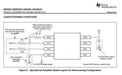
The caps in Mr. Mile schematic are not shown, here is a scrn shot from NE5532 datasheet, which gives a guideline for layout.
easy to solder x7r ceramic smd on the bottom as I think in your board, you have power and ground traces running under the op amp.
All the best for your build.
regards
Prasi
Attachments
Hello Willy,
The caps in Mr. Mile schematic are not shown, here is a scrn shot from NE5532 datasheet, which gives a guideline for layout.
easy to solder x7r ceramic smd on the bottom as I think in your board, you have power and ground traces running under the op amp.
All the best for your build.
regards
Prasi
Hi Prasi,
Thanks and I Agree with you for Texas Instrument opamp, but in other brand not stated.
Regards,
Yes..Hello mantrieSolder,
here you go. Is this what you were looking for?
regards
Prasi
I want to try build with iron masking technique
thank you very much sir
Regard
Good JobI will try soon...
Pdf file please...
A40 power supply help
Hi Mile Sir and other experts,
I am planning to reuse the toroidal trafo of my dead Denon PMA1520 amplifier for the Apex A40 build. The trafo specification is 44-0-44 volt AC (no VA specification). I am getting around 62V DC after rectification.
Should I make any changes to the A40 scheme to use this trafo? Or could I directly use this without any modification to the scheme.
Please help me out on this.
Thank you.
Sha
Attachments
Mr. Mile,
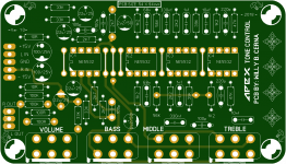
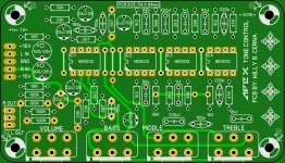
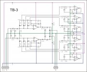
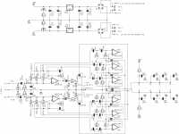
A version of TB-3 with supply. Could you please check the schematic ? Is layout ok?, although quickly done and not refined...
blue is top ground plane. not diy friendly, but cheap to manufacture.
regards
Prasi
A version of TB-3 with supply. Could you please check the schematic ? Is layout ok?, although quickly done and not refined...
blue is top ground plane. not diy friendly, but cheap to manufacture.
regards
Prasi
Attachments
Hi Cornel,
Although I couldn't locate sch, from layout posted here
100W Ultimate Fidelity Amplifier
and here
100W Ultimate Fidelity Amplifier
I think 42V might be too high for BD139 and BC550/560.
and from the second layout, it is evident that you can use IRFP240/9240
sorry i am not able to help you further, may be olaf or apex will shed more light?
regards
Prasi
Hi Prasi
I searched in thread and I found some answers. Fist I will replace IRF's, check connections in boards. I am affraid to have a shortcircuit and don't see it. Still remains bias adjust. I will change rezistors value in VAS. What can go wrong ? Worst case scenario: to burns some componets, but I find the
the answer to the questionans: increases or decreases
All this will take some time because I'm working on this project after timework and in weekend family first.
B plan: build AX9
Regards
Hello Cornel,
Sounds like a good plan, all the best. Also if you are not doing it already, power the circuit up with mains bulb tester (MBT) before the transformer and safety resistors (100ohm 1-2W in line with +/- amplifier supply) to minimize chances of burning components and smoke. If the bulb lights brightly, you will know you have a short.
regards
Prasi
MBT link
Light Bulb Tester
- Home
- Amplifiers
- Solid State
- 100W Ultimate Fidelity Amplifier