@Bahrad
With your measurements @ testing points TP A-B (your pic),
with emitors resistors 2x0R33 @25mV is quiet good,
this is 35-38mA per output BJT pair
try to biasing @50mV, this is 50mV/0R66=75mA per output BJT pair,
if the main heatsink maintens lower temp then 55°C.
This is the temp that you can touch the heatsink with your fingers
for more then approximately 5sec
or measure precisely with adequate temp-meter.
You will have less crossover distorsion, better THD...
thanks mr dragan
i built second channel today and both channel are work very good
")

i will install to heatsink tommorow
i measured voltage on 15v zeners pins
in bot diode voltage were 7v
is this correct?
But why zener pins voltage is 7v in my amplis?it is not,you should have 15V on zener diodes, that is power supply for IC...
My power supply is +/-50v
Someone had asked me through PM regarding procedure for bias of APEX FX-8 Bimo Mod. Posting here for convenience of others. Please feel free to edit and re-post.
Procedure for bias.
1. you will need 2 nos. of 10ohm 1W/2W resistors.
1a. turn the trim pot so that resistance between first and third leg of trimmer is approx 250 ohm.
2. Connect one lead these 10ohm resistors in series with your + and - rail wires of psu.
3. connect the other lead of resistors to amplifier +/- supply connector on amp pcb.
4. switch on supply and measure the voltage drop across these rail resistors.
4a. measure the voltage between spk out and ground. this is offset. it should be less than +/-15-30mV. Good matching of Hfe of i/p transistor pair (Q1/Q3) will ensure that offset is close to zero.
5. total quiescient current is given by I= V/10ohm
6. set the pot so that voltage drop across 10 ohm rail resistors is about 1V to 1.1 V.
7. Let the amp warm up for 1/2 an hour recheck the bias
8. Adjust pot if required to have voltage drop of 1 to 1.1 V.
9. This will ensure that you get a bias through o/p stage of approx. 100mA.
regards
Prasi.
Measure voltage before the zener resistor,measure and be sure you have instal the right value resistors and zeners,if it's ok check zeners.But why zener pins voltage is 7v in my amplis?
My power supply is +/-50v
If zeners are ok(and the right value) then you have overload somewhere these.
APEX AX14 DC output speaker
Hi!
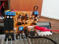
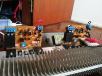
I just set up a pair of the AX14 amp and I'm starting the tests.
I connected the psu (+42 0 -42), connected the input ground to the pcb ground and to the ground of the chassis. I shorted the input signal to earth.
In the R33 resistor I set 10mV. But when I measure in the output for the speaker (negative on the ground and positive on the output) I have ~ 38V.
I already checked all the semiconductors.
Does anyone have any ideas?
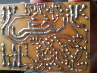
The first picture is only for the visualization of the tracks. All components were not yet assembled.
Hi!
I just set up a pair of the AX14 amp and I'm starting the tests.
I connected the psu (+42 0 -42), connected the input ground to the pcb ground and to the ground of the chassis. I shorted the input signal to earth.
In the R33 resistor I set 10mV. But when I measure in the output for the speaker (negative on the ground and positive on the output) I have ~ 38V.
I already checked all the semiconductors.
Does anyone have any ideas?
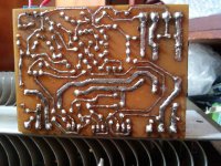
The first picture is only for the visualization of the tracks. All components were not yet assembled.
Attachments
connect gnd from input jack to the main PSU gnd, of both channels.
Sorry about that - I put a BC547 instead BC557. A newbie mistake!
Now, a have -12mV in the right channel and -19mV in the left channel. Is it OK?
Bias: 15.4mV
Sorry for bad English!
Yes,it's ok.Sorry about that - I put a BC547 instead BC557. A newbie mistake!
Now, a have -12mV in the right channel and -19mV in the left channel. Is it OK?
Bias: 15.4mV
Sorry for bad English!
Practically anything up to 50 mV(others say 100mV) it's ok.
The less the better.
Last edited:
EX-14 Mod
Someone ask me to modify EX-14.
This is the simulation. I change to class AB.
The THD did not change significantly, because low open loop gain.
But slew rate is high enough. It should be use a good PSU, because
PSRR is not great.
This amplifier can use cheap output transistor like 2SC5200, but the PSU voltage must be at 35VDC.
Attachments
Yes,it's ok.
Practically anything up to 50 mV(others say 100mV) it's ok.
The less the better.
Thanks all!
The sound is great now! Awesome bass...
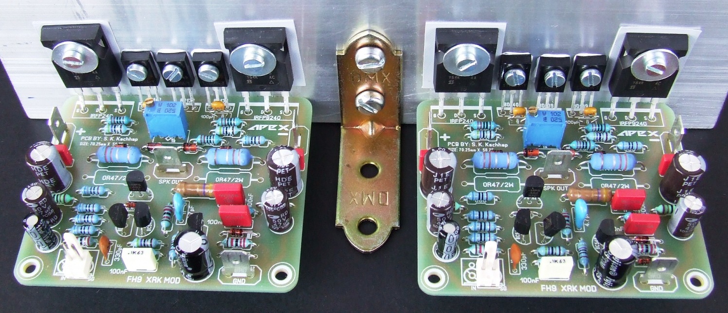
Another FH9 freshly packed and ready to serve. The sound is surprisingly good! Many thanks to Sonal Kunal for the pcb layout. The VAS transistors are KSC2690 KSA1220 because it's easier to mount fully isolated TO126. Bias is only 30mA (yes I know that it should be 100-150mA).
Attachments

Nice work Ivanlukic! The FH9 remains one of my favorite amps. Simple to build and sounds good beyond its modest appearance would indicate. Neat choice of drivers as I have never heard of KSC2690 and KSA1220 before. I wonder if KSC3503 and KAA1381 would work as well? These look very nice as they handle a larger current like a BD139/140 but with fully insulated package. They could be very nice as final outputs in a headphone amp?
They are rated high enough in voltage that if you had installed 63v rated power caps you could run at +/-53v for FH9HV for 125w/ch amp. Although with 50v rated caps you could run st 49v rails and be right up there at 100w/ch. One comment: try to put film caps in for the 100pF at the drivers instead of ceramic MLCC's unless NP0/C0G - it will improve the sound with lower distortion. Also, definitely out a film cap for the 330pF RFI input filter cap. That is definitely a source of improving the sound. They are subtle but taken together will improve the sound.

They are rated high enough in voltage that if you had installed 63v rated power caps you could run at +/-53v for FH9HV for 125w/ch amp. Although with 50v rated caps you could run st 49v rails and be right up there at 100w/ch. One comment: try to put film caps in for the 100pF at the drivers instead of ceramic MLCC's unless NP0/C0G - it will improve the sound with lower distortion. Also, definitely out a film cap for the 330pF RFI input filter cap. That is definitely a source of improving the sound. They are subtle but taken together will improve the sound.
Last edited:
Unfortunately KSC2690 KSA1220 are obsolete. They are way better than BD pair. And very practical because of fully isolated case. C3503 and A1381 are even better. This is probably the first amp that I liked with passive pre (only 20k volume pot at the input). I must admit that I like the sound of HEX fets even better than Laterals. Only small improvement that can be done with this amp is to use Vbe multiplier as suggested in Bob Cordell's book in the chapter about MOSFET amps. Vbe multiplier in FH9 is more like standard Vbe multiplier for bipolar outputs. It overcompensates when used with HEX fets, but this is probably good for reliability.
Small MLCC caps at the drivers are NP0 class!
Small MLCC caps at the drivers are NP0 class!
Last edited:
Hi Ivan, congratulations to your beautiful PCB's!
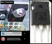
I noticed your IRFP MOSFET's are exactly the same I could buy from our local shop and measured the base to be 1,2mm, they told these MOSEFT's are made by Taiwan Semiconductor and buy them from a dealer in Europe but wasn't keen on disclosing from whom, I found two companies in Taiwan but I am not sure which one, does anyone know exactly who is manufacturing these FET's?
I noticed these can be bought for an "affordable" price from China.
I hope they work well for you.
Attachments
these are completely different devices and not interchangeable.Unfortunately KSC2690 KSA1220 are obsolete............C3503 and A1381 are even better............
The 2sa1220/c2690 is a driver transistor P=20W, Ic=1.2A, Cob=26pF
The 2sa1381/c3503 is a VAS/pre-driver P=7W, Ic=0.1A, Cob=2.6pF
Hi Ivan, congratulations to your beautiful PCB's!
I noticed your IRFP MOSFET's are exactly the same I could buy from our local shop and measured the base to be 1,2mm, they told these MOSEFT's are made by Taiwan Semiconductor and buy them from a dealer in Europe but wasn't keen on disclosing from whom, I found two companies in Taiwan but I am not sure which one, does anyone know exactly who is manufacturing these FET's?
I noticed these can be bought for an "affordable" price from China.
I hope they work well for you.
These are my favorite brand HEXFET. When I buy them from Mouser/Digikey the company listed is Vishay.
Only small improvement that can be done with this amp is to use Vbe multiplier as suggested in Bob Cordell's book in the chapter about MOSFET amps. Vbe multiplier in FH9 is more like standard Vbe multiplier for bipolar outputs. It overcompensates when used with HEX fets, but this is probably good for reliability.
I think there is a suggestion for a revised Vbe multiplier in the CFH7 thread. It involves adding a yellow LED and resistor change for a BD139.
Small MLCC caps at the drivers are NP0 class!
Good! My NP0 MLCC radials are usually blue and yellow is the X7R but that depends on supplier.
Last edited:
these are completely different devices and not interchangeable.
The 2sa1220/c2690 is a driver transistor P=20W, Ic=1.2A, Cob=26pF
The 2sa1381/c3503 is a VAS/pre-driver P=7W, Ic=0.1A, Cob=2.6pF
I think in the case of FH9, the gates of IRFPs can be driven just fine with KSC3503/JSA1381, as is the case for CFH7/9.
IRFP I used are sold to me as Vishay. They work great. I never heard about fake IRFP and think that one can buy these that I used with confidence. I payed less than 2 dollars for each transistor. I think that they are available and affordable in most countries.
Few years ago there was the VSSA thread. Jason Kueteman used 2690/1220 pair for the VAS stage while suggested ones were 3503/1381. There was no complaints concerning 2690/1220. 3503/1381 are better for the positions where we need good linearity with lower currents. But in FH9 it is no problem to use 3503/1381. Output transistors in FH9 are driven from VAS stage and all these transistors will work fine including BD139/140.
Few years ago there was the VSSA thread. Jason Kueteman used 2690/1220 pair for the VAS stage while suggested ones were 3503/1381. There was no complaints concerning 2690/1220. 3503/1381 are better for the positions where we need good linearity with lower currents. But in FH9 it is no problem to use 3503/1381. Output transistors in FH9 are driven from VAS stage and all these transistors will work fine including BD139/140.
Last edited:
- Home
- Amplifiers
- Solid State
- 100W Ultimate Fidelity Amplifier