Jay,
It's really not that hard to get an image from your camera or phone onto your computer for sharing your diy world.
This is a ridiculous hobby. I prefer to keep it private
 If I have the tools there might be nothing to stop me from taking and posting one or two pictures, but nothing to motivate me so far to get these tools. This is a hobby that I will stop if I can... And I'm not those guys who post pictures in Facebook
 So a description of your methods to get the PCB smaller are somewhat achievable in words - as they say though, a picture is worth a thousand words. Many people would benefit from seeing how you actually achieve this.
I use hand drawing, so no Eagle file or the like to post. My etched PCB is based on perforated board, the smallest one that fit the standard opamp pins... You arrange your components around without giving any space wasted, and you will get smaller PCB. If you do this, your LTP transistors should touch each other...
That's fine that you say you prefer not to post pics. Just a waste of knowledge that could be shared more effectively - but that's the last I will say of it.
Ok, I will try a P2P on a small perfboard for the preamp. On the second FX8, I measured about 20 input transistors and got Hfe matched to within 4 out of 400 (1%) and made the LTP's bent over and touching. The offset on this one is very good at only -6mV vs -16mV for the last one which was randomly selected. It makes a difference but a pain to measure all of those.
I will skip all the Zeners next time I need to make a lateral FET build smaller or not fret if I don't have any. Circuit will work as it had built in ones.
Has anyone built the preamp yet? Seems like just another stage of FX8 sans last two stages. How does it sound?
http://www.diyaudio.com/forums/soli...imate-fidelity-amplifier-696.html#post4677661
http://www.diyaudio.com/forums/soli...imate-fidelity-amplifier-696.html#post4677661
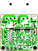
Does anyone have a schematic of the board that I actually had built because it's quite different from the posted schematic provided by Apex. It has pots, Zeners, BD139/149 instead of BC639 etc. then I can figure out what to leave out when assembling it.
I don't have the schematic but I have marked up an image to show the values you need to change and showing the parts missing that are not to be installed. Your need to add 4 jumpers. I tried to show all the changes in red. The two 47uF caps on the rails could probably be left off if you want. They are not on any of the schematics. Hope this helps.
EDIT: Of course you will have to use a 100k pot in front of the input
Attachments
Last edited:
I don't have the schematic but I have marked up an image to show the values you need to change and showing the parts missing that are not to be installed. Your need to add 4 jumpers. I tried to show all the changes in red. The two 47uF caps on the rails could probably be left off if you want. They are not on any of the schematics. Hope this helps.
EDIT: Of course you will have to use a 100k pot in front of the input
Thanks! Exactly the sort of help I was looking for.
FX8
is 2sc2240 a good replacement for bc546?
2SC2240
Collector/base voltage VCBO 120 V
Collector/emitter voltage VCEO 120 V
Emitter/base voltage VEBO 5V
DC Current Gain HFE 200-700
BC546
Collector/Emitter Voltage 65V
Collector/Base Voltage 80 V
Emitter/Base Voltage 6.0 Vdc
DC Current Gain HFE 110-450
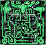
lastly here is a better layout of my fx8
is 2sc2240 a good replacement for bc546?
2SC2240
Collector/base voltage VCBO 120 V
Collector/emitter voltage VCEO 120 V
Emitter/base voltage VEBO 5V
DC Current Gain HFE 200-700
BC546
Collector/Emitter Voltage 65V
Collector/Base Voltage 80 V
Emitter/Base Voltage 6.0 Vdc
DC Current Gain HFE 110-450
lastly here is a better layout of my fx8
Attachments
2sa/c To92 transistors are ECBis 2sc2240 a good replacement for bc546?
2SC2240
Collector/base voltage VCBO 120 V
Collector/emitter voltage VCEO 120 V
Emitter/base voltage VEBO 5V
DC Current Gain HFE 200-700
BC546
Collector/Emitter Voltage 65V
Collector/Base Voltage 80 V
Emitter/Base Voltage 6.0 Vdc
DC Current Gain HFE 110-450
lastly here is a better layout of my fx8
BC54x are CBE
they don't fit !!!
2sa/c To92 transistors are ECB
BC54x are CBE
they don't fit !!!
yes AndrewT i'm aware of that.. what i'm asking is "if it is a good replacement".
is 2sc2240 a good replacement for bc546?
2SC2240
Collector/base voltage VCBO 120 V
Collector/emitter voltage VCEO 120 V
Emitter/base voltage VEBO 5V
DC Current Gain HFE 200-700
BC546
Collector/Emitter Voltage 65V
Collector/Base Voltage 80 V
Emitter/Base Voltage 6.0 Vdc
DC Current Gain HFE 110-450
lastly here is a better layout of my fx8
What are the two 5.5mm holes for in the center of the board?
Why do you claim this is a better layout?
What are the two 5.5mm holes for in the center of the board?
Why do you claim this is a better layout?
for fixing the output transistor.. i said "My FX8" i didn't claim it is better than other.
for fixing the output transistor.. i said "My FX8" i didn't claim it is better than other.
OK, I see now. I hadn't noticed that you reversed the pinout of the output transistors. I like it. This will be very nice for a multichannel amp. Thanks for sharing.
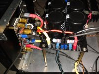
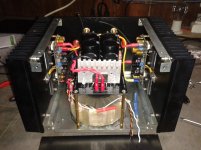
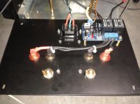
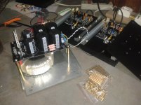
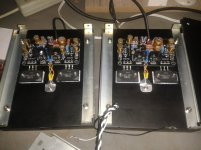
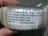
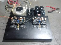
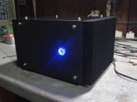
AX11 in action
https://www.youtube.com/watch?v=Zj8FkU1qIt8
Thanks for sharing!
Here is more pictures
Attachments
-
 IMG_20160212_211556.jpg470.7 KB · Views: 282
 -
 IMG_20160212_221203.jpg443.1 KB · Views: 266
 -
 IMG_20160212_211536.jpg477.6 KB · Views: 657
 -
 IMG_20160210_210514.jpg441.9 KB · Views: 691
 -
 IMG_20160210_210535.jpg457.7 KB · Views: 759
 -
 IMG_20160207_214738.jpg753.9 KB · Views: 807
 -
 IMG_20160207_214105.jpg839.4 KB · Views: 873
 -
 IMG_20160212_225919.jpg709.2 KB · Views: 266
That keeps it small. I think 100uF needs to be rated full rail voltage.
That cap sees <1V
That keeps it small. I think 100uF needs to be rated full rail voltage.
it should be 1000uF16V, if it can be fitted.
- Home
- Amplifiers
- Solid State
- 100W Ultimate Fidelity Amplifier