FX8 is AX11 with lateral mosfet OS, not tested.
Regards
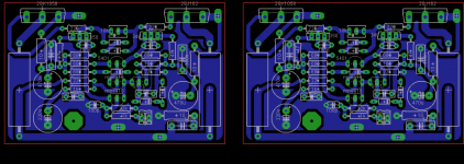
I build and tested fx8..I use 2sk1058 & 2sj162 lateral mosfets..no need thermal comp.
I m used 2x 1n4148 for bias current.(you can add 5-10k trimpot if you want).about 130ma each channel..bd139-140 for driver..mpsa18 for IPS.
Sound is nice..stable for any frequance.
http://www.diyaudio.com/forums/attachment.php?attachmentid=529284&stc=1&d=1454615627
Attachments
Last edited:
I build and tested fx8..I use 2sk1058 & 2sj162 lateral mosfets..no need thermal comp.
I m used 2x 1n4148 for bias current.(you can add 5-10k trimpot if you want).about 130ma each channel..bd139-140 for driver..mpsa18 for IPS.
Sound is nice..stable for any frequance.
http://www.diyaudio.com/forums/attachment.php?attachmentid=529284&stc=1&d=1454615627
Nice work, thank you.
Regards
Have you measured the elco caps? Mine only have 2.5mm pitch.
I think he said 1k for the trimmer.
Hi Terry,
Its a draft layout, diameter of cap is more important. once approved by Mr. Mile, I can make caps multi-pitch and also improve upon trace layout, etc.
reg
Prasi
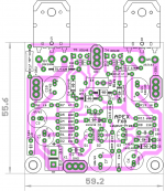
Hi prasi, layout can be done without jumper, attached picture will help.
Remove R3 place it where R5 is and move R4 - R5 lower.
Regards,
Sonal Kunal
Thank you for your efforts Sonal. Here is the modified layout as per your suggestions. Sometimes you need fresh set of eyes, to look from a different perspective
") + I'm not that gifted in lay-outing.
+ I'm not that gifted in lay-outing.reg
Prasi
P.S. if anyone wants toner transfer files, i will post here.
Attachments
Last edited:
Hi sir willjj78 pls share ax20 5pair output pcb layout copper side files
https://www.dropbox.com/s/umo3y1oel74svil/AX-20 Rev. 2.2.rar?dl=0
Thank you for your efforts Sonal. Here is the modified layout as per your suggestions. Sometimes you need fresh set of eyes, to look from a different perspective
reg
Prasi
P.S. if anyone wants toner transfer files, i will post here.
Hi,
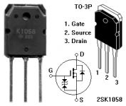
You dont need d4-d5-d6-d7. because it has got internal if you use 2sk1058-2sj162
Attachments
AX 20 #6468 PCB
Hi andrew, its AX-14 with 2 pair OP.
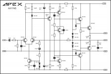
AX11 with Non Switching circuit.
What is advantage compare to AX11?
What is advantage compare to AX11?
'In a non-switching class AB amplifier none of the output transistors is switched off completely at any time.
In a class A amplifier normally a current increase in one output transistor goes together with an (almost) equal decrease of current in the other.
In a class AB amplifier normally an increase in current through one output transistor (with approx the bias current) makes the other transistor non-conducting.
In a non-switching cass AB amplifier an increase in current through one output transistor lowers the current in the other transistor in a non-linear way and such that it will not go to zero. The advantage is that this transistor will not be reversed biased (as will happen in normal class AB) and this makes switching on again much faster.
Steven'
Sprint files.
Please post the sprint files if you would Sonal!
Thank you in advance.
Pdf files for AX-20. If any one wants sprint file I can post them.
Hi Mile, do you have layout for other version of FX8 => FX8SCF?
Regards
Sonal Kunal
Please post the sprint files if you would Sonal!
Thank you in advance.
6 diodes and two resistors addeted to ax11?AX11 with Non Switching circuit.
6 diodes and two resistors addeted to ax11?
Yes and with another two diodes and two zeners over current limiter was add,
Attachments
You have test this?I'm glad you've applied the old solution ( nonswitching ) proposed by me ( in another subject power audio ) into a your ax11 schematic .
I hope the audio results are up to expectations .
An externally hosted image should be here but it was not working when we last tested it.
This is SVI from Technics. I like the sound .
An externally hosted image should be here but it was not working when we last tested it.
This is Technics su V7. It should work..
I'm sorry if I was wrong.
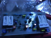
It's Alive !!
Hi,
It's alive and Kicking (singing rather) !! For the last two days been working on the same and finally it's up and running.Started working in one go,Didn't have to do any debugging or such (had made sure of that by triple checking each and every component,Soldering etc).
Followed all the usual precautions and such,Also followed Dragon's protocol ! Connected the Amp with Resistors (50 Ohm 25W) and 1Amp fuse as Dragon had advised.
Heard it briefly and it does sound wonderful,Will refrain to comment on the sound as it will have to be heard more and have to burn-in the components to get the final sound of the Amp.
But on a brief note :
1) Very smooth and clean highs (almost neutral already making me wonder when its fully burnt-in will it go down ??),No sign grain or siblance or any other artifacts.
2) Mid is very much on the dot, Airy,focused and silky smooth without harshness or Midbass bloat.
3) Bass is very controlled and agile (but did feel it to be a tad bit less compared another Amp using the same 5200/1943 pair).
Now that all the good things are covered let me come to few nig/nags or snags !
1) As mentioned had used 50 Ohm 25W resistor with a 40-0-40V supply (25V,5A trafo),The voltage drop across it was ranging from .6-.9V as opposed to what dragon said (max.3-.5V)

2) For the life of me Am not able to measure the bias (voltage across the .33Ohm),It just sits @ 0V or 0.1.Have a autorange DMM and it refuses to... Not sure whether it's the DMM fault or (cause was able to measure the V drop across the Power resistor),So have kept the 1K bias preset to the middle at 500 Ohm.Also tried to see if varying it has any effect but unless I bring it to zero no other value has any effect,If I bring to zero the Relay trips and switches off.
PS: Even with this setting there absolutely is no heat. I,e the main heat sink inspite of being a puny one doesn't even get warm even after an hour of playing,neither does the 340/350. Kept checking it repeatedly at regular intervals.
3)Between the two channels,One channel has a switch on delay and is more sensitive (when testing with resistors it kept switching on and off),But the other one has no delay and switches immediately (switch on thump heard in the speaker). Have checked the resistors,transistors and all,everything is almost matched (have not taken any voltage reading though). The one which switches on immediately takes more time switch off than the one which turns on with delay.
In the post #79 Mr.Mile recommends this for a similar supply for the relay circuit
Should I change ? if yes then why only one channel affected ??
4) Although no hum or such noises,there a tiny noise when one squints closely at the tweeter (guessing cause of the test cabinet and wiring).
I want to correct the switch on delay issue on one channel as it's very much bothering me,So please advise.
The cabinet is and the whole wiring is temp,will be making a suitable cabinet soon (still not decided whether to go for a pre-power combo or make it a integrated with only volume).

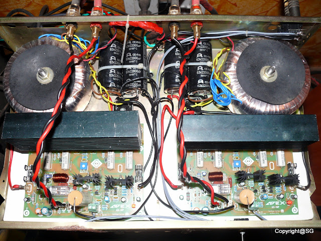


This is my setup currently,Denon 755AR CDP with discrete Op-Amps,My own Hand braided Interconnect,Speaker Cables.
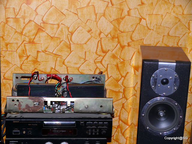
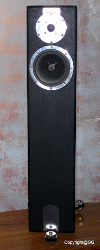
This is my latest DIY TL towers : DIYed to the core,DIY made drivers (Custom machined parts for the drivers including the tweeter faceplate),Custom machined Spikes with base plate.

So much more I wanted to write and post but in the exciment forgot it all !
Anyways thanks once again to,Juan for the PCB files and help. Dragon for the help he provided and offcourse Mr.Mile without whose circuit none of this would've happened !
Regards.
Hi,
It's alive and Kicking (singing rather) !! For the last two days been working on the same and finally it's up and running.Started working in one go,Didn't have to do any debugging or such (had made sure of that by triple checking each and every component,Soldering etc).
Followed all the usual precautions and such,Also followed Dragon's protocol
! Connected the Amp with Resistors (50 Ohm 25W) and 1Amp fuse as Dragon had advised.Heard it briefly and it does sound wonderful,Will refrain to comment on the sound as it will have to be heard more and have to burn-in the components to get the final sound of the Amp.
But on a brief note :
1) Very smooth and clean highs (almost neutral already making me wonder when its fully burnt-in will it go down ??),No sign grain or siblance or any other artifacts.
2) Mid is very much on the dot, Airy,focused and silky smooth without harshness or Midbass bloat.
3) Bass is very controlled and agile (but did feel it to be a tad bit less compared another Amp using the same 5200/1943 pair).
Now that all the good things are covered let me come to few nig/nags or snags !
1) As mentioned had used 50 Ohm 25W resistor with a 40-0-40V supply (25V,5A trafo),The voltage drop across it was ranging from .6-.9V as opposed to what dragon said (max.3-.5V)
2) For the life of me Am not able to measure the bias (voltage across the .33Ohm),It just sits @ 0V or 0.1.Have a autorange DMM and it refuses to... Not sure whether it's the DMM fault or (cause was able to measure the V drop across the Power resistor),So have kept the 1K bias preset to the middle at 500 Ohm.Also tried to see if varying it has any effect but unless I bring it to zero no other value has any effect,If I bring to zero the Relay trips and switches off.
PS: Even with this setting there absolutely is no heat. I,e the main heat sink inspite of being a puny one doesn't even get warm even after an hour of playing,neither does the 340/350. Kept checking it repeatedly at regular intervals.
3)Between the two channels,One channel has a switch on delay and is more sensitive (when testing with resistors it kept switching on and off),But the other one has no delay and switches immediately (switch on thump heard in the speaker). Have checked the resistors,transistors and all,everything is almost matched (have not taken any voltage reading though). The one which switches on immediately takes more time switch off than the one which turns on with delay.
In the post #79 Mr.Mile recommends this for a similar supply for the relay circuit
1 Replace 1,5k/5w with 330R/2W for relay
2 Replace 0,1R/5W with 0,22R/5W for short-circuit detect
3 Replace 220k with 47k for DC detect
Rest will work with 35V DC, 6k8/1W for LED can be replaced with 3k9, but not necessary.
Should I change ? if yes then why only one channel affected ??
4) Although no hum or such noises,there a tiny noise when one squints closely at the tweeter (guessing cause of the test cabinet and wiring).
I want to correct the switch on delay issue on one channel as it's very much bothering me,So please advise.
The cabinet is and the whole wiring is temp,will be making a suitable cabinet soon (still not decided whether to go for a pre-power combo or make it a integrated with only volume).
This is my setup currently,Denon 755AR CDP with discrete Op-Amps,My own Hand braided Interconnect,Speaker Cables.
This is my latest DIY TL towers : DIYed to the core,DIY made drivers (Custom machined parts for the drivers including the tweeter faceplate),Custom machined Spikes with base plate.
So much more I wanted to write and post but in the exciment forgot it all !
Anyways thanks once again to,Juan for the PCB files and help. Dragon for the help he provided and offcourse Mr.Mile without whose circuit none of this would've happened !
Regards.
Last edited:
- Home
- Amplifiers
- Solid State
- 100W Ultimate Fidelity Amplifier