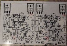
I tried to do a layout for the FET A2. If one or more of you kind folk would look it over and let me know if you see any errors I would appreciate it.
Blessings, Terry
Are Z3 and Z4 connected correctly in the schematic? It looks like they are connected to output instead of ground. Op amp supply voltage would move with output voltage as is.
Last edited:
Are Z3 and Z4 connected correctly in the schematic? It looks like they are connected to output instead of ground.Are Z3 and Z4 connected correctly in the schematic? It looks like they are connected to output instead of ground. Op amp supply voltage would move with output voltage as is.
Agree
I tried to do a layout for the FET A2. If one or more of you kind folk would look it over and let me know if you see any errors I would appreciate it.
Blessings, Terry
Track missing...
Attachments
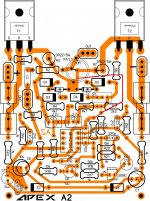
D3 and D4 should be in contact with heatsink.
Ah yes, I forgot we discussed thermal compensation earlier. That wasn't needed with the laterals.I will have to re-think this.
I wondered that too, but that is the way it is in the original and it seems to work fine. By the way, I raised the 36R to 39R and I have plenty of gain.Are Z3 and Z4 connected correctly in the schematic? It looks like they are connected to output instead of ground. Op amp supply voltage would move with output voltage as is.
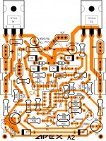
Track missing...
Oops, I forgot to put that back. Good catch. Let me try to rework this and see if I can find a solution for the thermal issue while I'm at it. This is more complicated than the circuit with the laterals.
I tried to do a layout for the FET A2. If one or more of you kind folk would look it over and let me know if you see any errors I would appreciate it.
Blessings, Terry
Hi Terry,
Dont have eagle eyes, ( for that I need to lay it out in eagle
") )but I feel the traces can be thicker after emitter resistors .
)but I feel the traces can be thicker after emitter resistors . reg
Prasi
Hi Terry,
Dont have eagle eyes, ( for that I need to lay it out in eagle
reg
Prasi
Good idea.
Cant adjust the bias with 1K ... and still confuse
Can you post the value of trimpot and resistor in series with trimpot.
Attachments
Can you post the value of trimpot and resistor in series with trimpot.
Yes... i use that schenatic, if R 1 K changes with 220 the bias can adjust
Yes... i use that schenatic, if R 1 K changes with 220 the bias can adjust
If you are using 680Ω in series with 1k trimpot then reduce 680Ω to 560Ω, 470Ω, 390Ω or 330Ω. Also check voltage between collector and emitter of BD139 when trimpot is fully turned CCW, voltage should increase when turned CW.
If you are using 680Ω in series with 1k trimpot then reduce 680Ω to 560Ω, 470Ω, 390Ω or 330Ω. Also check voltage between collector and emitter of BD139 when trimpot is fully turned CCW, voltage should increase when turned CW.
I looked back through my build and in post 4270 I started a discussion with Mile about setting the bias. What we found may be of some help.
Blessings, Terry
Track missing...
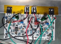
Here it is with the missing trace fixed. I may try flying the two diodes on wires and install them in a small plate ala Leach and attach it to one of the mounting bolts of an output.
Attachments
From his question I assumed he could not adjust bias with trimpot fully turned CW.
Hmmm, I've built two of them and they can be biased so either his devices are way different than the ones I used or there is something wrong.
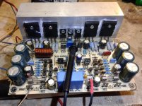
I etched a pair for the A2 FET. I'll try to get them populated tomorrow.
Attachments
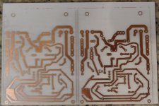
I etched a pair for the A2 FET. I'll try to get them populated tomorrow.
Nice work.
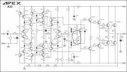
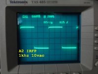
A2 with IRFP240/9240 Specifications (Simulated):
Rail Voltage +/-55VDC.
SNR 105dB@1KHz
PSRR -120dB
BW 5Hz - 52KHz
SR 80V/usec
THD 10WRMS@8R0 0,007%, 150WRMS@8R0 0,02%
Clipping is about 52-53Vpeak.
Regards
Last edited:
Hi Mile,Nice work.
A2 with IRFP240/9240 Specifications (Simulated):
Rail Voltage +/-55VDC.
SNR 105dB@1KHz
PSRR -120dB
BW 5Hz - 52KHz
SR 80V/usec
THD 10WRMS@8R0 0,007%, 150WRMS@8R0 0,02%
Clipping is about 52-53Vpeak.
Regards
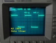
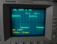
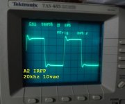
The A IRFP is singing. However it need a little help. See attached scope shots. Looks like it needs compensation changes.
Blessings, Terry
Attachments
- Home
- Amplifiers
- Solid State
- 100W Ultimate Fidelity Amplifier