Hi Mile,
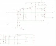
Can you please check the layout in post #5504? I am testing it and I have 150mV offset. I measured and pin #4 is pulled down to 0.3V. If I pull the IC then pin #4 goes to 15V but pin #7 drops to 3V and the offset goes to 15V. If my layout is right then something is wrong with the circuit.
Thanks, TerryThe -IN is sensitive to pick up.
Keep it's resistor very close to the -IN pin.
What is rail voltage? Replace R17 and R18 with 470R/2W to get +15V on pin 7 and -15V on pin 4... can you post pictures?
Hi c08bm,
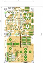
shouldnt the PGND be connected with the drain of mosfets as in schematic and alexmm layout ?
regards'
prasi
I considered ground to be linked on PSU, but it can go also with grounds linked on protection board
Attachments
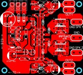
Alex is according to schematic,c08bm isn't.
Where is c08bm's off from the schematic?
Last edited:
What is rail voltage? Replace R17 and R18 with 470R/2W to get +15V on pin 7 and -15V on pin 4... can you post pictures?
Hi Mile,
That seems to be the answer. I was testing at +-47V. I raised it to +-55V and now I have +-16V at the zeners. However, 39V/1k is 1.5w so obviously my 1W resistors are not sufficient. I may take your advice and lower R17 and R18 anyway because I think +-55V is a little high for a single pair of outputs.
With single pair use +/-35V, +/-40V is maximum, and R17,18 can be 470R/2W...
I considered ground to be linked on PSU, but it can go also with grounds linked on protection board
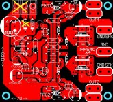
You can use single AC and only one 1N4007 to supply protect and with only one GND connection from main PSU.
Attachments
You can use single AC and only one 1N4007 to supply protect and with only one GND connection from main PSU.
Yes, but all ground traces must be connected on the board right?
You can use single AC and only one 1N4007 to supply protect and with only one GND connection from main PSU.
Is these not the PS ground (green arrow)?
I ask because that is connected to the capacitor etc and you X-ed out ..
I think we need that
Attachments

Yes, but all ground traces must be connected on the board right?
Yes like on pcb from post #5562
You can use single AC and only one 1N4007 to supply protect and with only one GND connection from main PSU.
Like this? I have connected the ground traces on the PSU to Protect with a jumper. only one of the ground connectors can be used here (jumper, 2 pin connector or faston connector).
Attachments
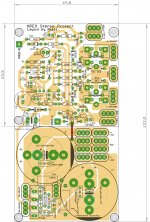
Like this? I have connected the ground traces on the PSU to Protect with a jumper. only one of the ground connectors can be used here (jumper, 2 pin connector or faston connector).
Yes, like that and use only PGND to psu GND connection or use red jumper and cut this trace.
Attachments
Last edited:
I just tested the protection circuit. It takes at least 9Vdc on the output to activate it and that takes almost a full second. 12vdc takes just as long. Shorting the speaker terminals does nothing. I don't have an amp hooked up to it so that may make a difference.
oops!.(speakers would be fried by the time protect comes into play. ) may be some components need adjustment in values, Mr. Mile can suggest something.
reg
prasi
With single pair use +/-35V, +/-40V is maximum, and R17,18 can be 470R/2W...
Hii Mile.
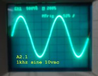
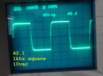
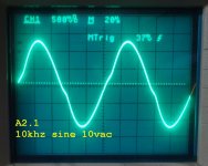
I discovered the issue with the zeners. I didn't have the input shorted. Once I did that the offset issue went away. However there are other issues that need to be worked out. Bias is too low. Only 26mA per rail at the fuse. Gain is very low, only about 16x. Square waves are very rounded. Do you have some recommendations?
Thanks, Terry
Attachments
I just tested the protection circuit. It takes at least 9Vdc on the output to activate it and that takes almost a full second. 12vdc takes just as long. Shorting the speaker terminals does nothing. I don't have an amp hooked up to it so that may make a difference.
Lowering 470uf should make protection faster.
Pro pin must be connected across positive emitor resistor for short circuit detector to work.One way to test it is to short speaker terminals and put pro pin to positive voltage
Last edited:
the maximum output power is directly related to the power of the installed output devices.Hi Mile,
That seems to be the answer. I was testing at +-47V. I raised it to +-55V and now I have +-16V at the zeners. However, 39V/1k is 1.5w so obviously my 1W resistors are not sufficient. I may take your advice and lower R17 and R18 anyway because I think +-55V is a little high for a single pair of outputs.
The easiest way to determine the maximum output power is to use the following formula.
Maximum output Power (ClassAB) = total output device power dissiation capability divided by design factor.
For mosFET outputs the design factor is ~4
for BJT outputs the design factor is around 5 to 6.
eg.
use one pair of 200W BJT devices, then total dissipation capability is 400W.
The maximum power of a 1pair 200W device output stage is about 400/5 to 400/6 and that is roughly 80W to 67W
Use that to determine your supply rail voltage with the speaker load you intend to design for.
3pr of 150W BJT devices allows maximum power upto 900/5 to 6 = 180W to 150W
Last edited:
I just tested the protection circuit. It takes at least 9Vdc on the output to activate it and that takes almost a full second. 12vdc takes just as long. Shorting the speaker terminals does nothing. I don't have an amp hooked up to it so that may make a difference.
Remove 2k2 resistor (in parallel with 470uF) and protect will detect +/-1V DC offset, use 100uF instead 470uF if you want fast protect... Short circuit protect work only with amp and input signal connected.
Last edited:
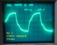
Hii Mile.
I discovered the issue with the zeners. I didn't have the input shorted. Once I did that the offset issue went away. However there are other issues that need to be worked out. Bias is too low. Only 26mA per rail at the fuse. Gain is very low, only about 16x. Square waves are very rounded. Do you have some recommendations?
Thanks, Terry
Use 500R (1k) trim pot instead 1N4148 diode to set bias. Amp is overcompensated for working prototype...
- Home
- Amplifiers
- Solid State
- 100W Ultimate Fidelity Amplifier