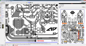
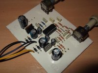
I was making a different layout this time I add the option for TO-3 and also regular transistors example (MJL3281A) can be use too I just wan to show you guys that with some patience this can be done I think looks pretty good")
Regards
Juan
Awww man....SWEET!!! time to place an order with Mouser... Can you please post the individual layers for etching?
Hey hello cjkpkg
I was checking the layout today and I made a mistake on the silkscreen only the top driver transistors I swap them by my mistake and I correct them here are the files please if any error some one see let me know so I can updated right away, I check many times but my eyes are tired the GND option is optional it does work for me because here in Puerto Rico we have the green wire ground same as USA 120 AC "live,neutral,ground"
the green wire connection does make the amplifier really quiet
yes .... I know .... is better to take it from the star GND of the power supply
ok the PD = pitch distance of the caps 22uF,100uF,2.2uF are 3.5mm, caps 220uF and 470uF is 5 mm PD the fuse clip part number is F6005CT-ND from DigiKey, the terminal block IN SGND input part number is 609-3927-ND, the tap connector part number is A24742-ND all from DigiKey
Regards
Juan
I was checking the layout today and I made a mistake
on the silkscreen only the top driver transistors I swap them by my mistake and I correct them here are the files please if any error some one see let me know so I can updated right away, I check many times but my eyes are tired the GND option is optional it does work for me because here in Puerto Rico we have the green wire ground same as USA 120 AC "live,neutral,ground"the green wire connection does make the amplifier really quiet
yes .... I know .... is better to take it from the star GND of the power supply
ok the PD = pitch distance of the caps 22uF,100uF,2.2uF are 3.5mm, caps 220uF and 470uF is 5 mm PD the fuse clip part number is F6005CT-ND from DigiKey, the terminal block IN SGND input part number is 609-3927-ND, the tap connector part number is A24742-ND all from DigiKey
Regards
Juan
Attachments
Last edited:
Hey hello cjkpkg
I was checking the layout today and I made a mistake
the green wire connection does make the amplifier really quiet
yes .... I know .... is better to take it from the star GND of the power supply
ok the PD = pitch distance of the caps 22uF,100uF,2.2uF are 3.5mm, caps 220uF and 470uF is 5 mm PD the fuse clip part number is F6005CT-ND from DigiKey, the terminal block IN SGND input part number is 609-3927-ND, the tap connector part number is A24742-ND all from DigiKey
Regards
Juan
Juan - you are The Man!!! This just moved up to me by next project.
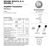
I have a spare 800W SMPS running +/- 60V - any concerns with the front end at this voltage? 2NXXX VS BCXXX?
Looks like if I sub BC546 for BC547 I should be good to go at +/-60V right?
Last edited:
Dear Mile,
If the comparison between AX and SR series specifically for bass tone, which one is lower for both character.
Thank you for your information.
Regard,
Yassud
I prefer SR series.
Juan - you are The Man!!! This just moved up to me by next project.
I have a spare 800W SMPS running +/- 60V - any concerns with the front end at this voltage? 2NXXX VS BCXXX?
Looks like if I sub BC546 for BC547 I should be good to go at +/-60V right?
Yes if I remember mister Miles mention that he tested with even higher rail voltage, not remember how much was I think was 90V
I use my AX-14T with only one pair with 53V rail voltage so with two pairs will work, just keep bias not too high I think is from 15mV to 20mV reading the 5 watts emitter resistors
I just check and with the NPN MJ15003 and PNP MJ15004 is possible to get about 380W to a 4 ohms load and the THD is pretty low
the range of the BC547 and 2NXXX should be fine
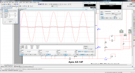
I simulated with 65V this time "yes I know is a simulation" let say will help to see what can happen
Regards
Juan
Attachments
Last edited:
Yes if I remember mister Miles mention that he tested with even higher rail voltage, not remember how much was I think was 90V
I use my AX-14T with only one pair with 53V rail voltage so with two pairs will work, just keep bias not too high I think is from 15mV to 20mV reading the 5 watts emitter resistors
I just check and with the NPN MJ15003 and PNP MJ15004 is possible to get about 380W to a 4 ohms load and the THD is pretty low
the range of the BC547 and 2NXXX should be fine
I simulated with 65V this time "yes I know is a simulation" let say will help to see what can happen
Regards
Juan
Hey Juan can you try fire up in simulation @ 20khz? will see the THD result.
Regards
Willy
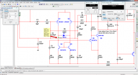
AX14 input stage with 2N5401 in LTP , BC547 in current miror and BC547/MJE350 ... super pairs in VAS can work with +/-120V dc rail.Juan - you are The Man!!! This just moved up to me by next project.
I have a spare 800W SMPS running +/- 60V - any concerns with the front end at this voltage? 2NXXX VS BCXXX?
Looks like if I sub BC546 for BC547 I should be good to go at +/-60V right?
Hey Juan can you try fire up in simulation @ 20khz? will see the THD result.
Regards
Willy
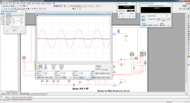
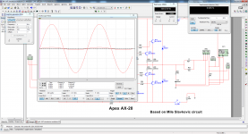
20KHz well to get lower THD I have to increase the rails to 90V so 0.882% THD
I don't think to drive and amp with 20KHz
yes I have to lower the input to 324mV tooRegards
Juan
Attachments
Last edited:
20KHz well to get lower THD I have to increase the rails to 90V so 0.882% THD
I don't think to drive and amp with 20KHz
Regards
Juan
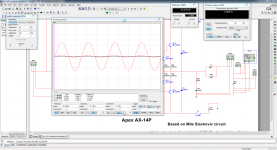
Try to change C9 and C10 from 10-22pf it will give better THD result.
Regards,
Willy
Try to change C9 and C10 from 10-22pf it will give better THD result.
Regards,
Willy
yes man wow it does goes down I change C9,C10 TO 10pF
Regards
Juan
Attachments
Not quite......................Looks like if I sub BC546 for BC547 I should be good to go at +/-60V right?
The input pair in some circumstances can be exposed to more voltage than what they have during normal quiescent operation.
Cordell and some others have given some guidance on protecting the input from excessive voltage.
I would not use a 60Vce0 device at 59Vce
Not quite.
The input pair in some circumstances can be exposed to more voltage than what they have during normal quiescent operation.
Cordell and some others have given some guidance on protecting the input from excessive voltage.
I would not use a 60Vce0 device at 59Vce
Vce on BC54X is under 1V, only 2N5401 is at rail voltage.
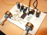
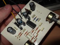
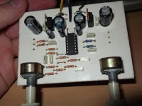
apex stereo preamp
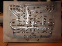
When printing the PCB it needs to increase by 3%
When printing the PCB it needs to increase by 3%
Attachments
-
PCB.pdf35.8 KB · Views: 425
-
RASPORED ELEMENATA.pdf41.7 KB · Views: 440
-
 DSCF0549.jpg733.7 KB · Views: 1,327
 -
 DSCF0553.jpg682.9 KB · Views: 1,231
 -
 DSCF0561.jpg774.7 KB · Views: 1,158
 -
 DSCF0571.jpg642.1 KB · Views: 290
 -
 DSCF0575.jpg681 KB · Views: 212
 -
 DSCF0581.jpg670.1 KB · Views: 164
 -
 DSCF0584.jpg703.5 KB · Views: 250
When printing the PCB it needs to increase by 3%
Nice work, thanks for this pcb design,
Regards
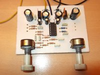
Hello guys here is the files again I just detailed a bit more and I include here the heat sink guide for the punch the marks for the drilling of the heat sink,
the negative of the speaker connection is there on the board but is better to take it from the power supply GND star, that is just for quick test, I did the simulation with 65V rails and it can give about 300W to a 4 ohms load so I think is plenty of juice for those Jazz drum moments ok here are the files please is some one see something let me know "we are not perfect" I will appreciate
Regards
Juan
the negative of the speaker connection is there on the board but is better to take it from the power supply GND star, that is just for quick test
, I did the simulation with 65V rails and it can give about 300W to a 4 ohms load so I think is plenty of juice for those Jazz drum moments ok here are the files please is some one see something let me know "we are not perfect" I will appreciate Regards
Juan
Attachments
- Home
- Amplifiers
- Solid State
- 100W Ultimate Fidelity Amplifier