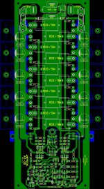
AX-20 5 Pairs
Good day Mr. Mile,
Glad to hear your inputs/comments of this AX-20 5 pairs.
Is there any changes needed on the VAS transistors if i use +/-78VDC??
Looking forward to hear from you.
Regards,
For bias adjust use 10R instead fuses and set 1V on them for single pair or 2V for two pairs. I suggest rail voltage +/-45V for single pair or +/-55V for two pairs (+/-65V 3 pairs, +/-75V 4 pairs, +/-85V 5 pairs and +/-95V 6 pairs or more).
DC offset is about +/-10mV.
Regards
Good day Mr. Mile,
Glad to hear your inputs/comments of this AX-20 5 pairs.
Is there any changes needed on the VAS transistors if i use +/-78VDC??
Looking forward to hear from you.
Regards,
Attachments
I have not experimented with a Rail to Rail decoupling cap. In my mind that makes sense for a fully balanced power amplifier (and presumably for a balanced opamp) where there is NO GROUND CURRENT returning from the load.
The two separate ground traces have a long connection that is NOT ZERO IMPEDANCE.
The HF decoupling ONLY works when the returning Ground Currents can pass through what is effectively a near zero impedance. The +ve side HF cap and the -ve side HF cap MUST be connected together to achieve the NEAR ZERO IMPEDANCE.
Hi Andrew,
This would be a good thing to do, however how could this be achieved without going double sided?
If the two ground traces from the outside were regrouped near the center, then the issue becomes the output traces.
A double sided board could solve this, at an extra cost, but in the end, to have the best result, this may be the only way to go.
Hi wil,
I was just wondering, what software are you using for this pcb layout?
If your software allows, perhaps going double sided would help arrange this ground trace issue and maybe even improve much further this whole grounding scheme.
Of course the double sided boards are more expensive, but really not that much and if the end result is worth it, then the extra expense is justified.
This layout is getting to look better and better. If there are enough diyers looking at making this amp, then a group buy might be a good idea to help bring down the pcb cost.
Hi wil,
I was just wondering, what software are you using for this pcb layout?
If your software allows, perhaps going double sided would help arrange this ground trace issue and maybe even improve much further this whole grounding scheme.
Of course the double sided boards are more expensive, but really not that much and if the end result is worth it, then the extra expense is justified.
This layout is getting to look better and better. If there are enough diyers looking at making this amp, then a group buy might be a good idea to help bring down the pcb cost.
Hi Spookydd,
I'm using sprint 6 and yes it support double sided trace, but i still want the board to be in single sided and diy friendly as possible....
Group buy with Mr. Mile approval using AX20 would be a great step forward to build this project....
Gootee has just posted this infoI have not experimented with a Rail to Rail decoupling cap. In my mind that makes sense for a fully balanced power amplifier (and presumably for a balanced opamp) where there is NO GROUND CURRENT returning from the load.................
http://www.diyaudio.com/forums/power-supplies/240955-resevoir-capacitors-chip-amps.html#post3632628
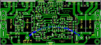
Just playing my sprint with this one...
You can try with this one...
")
Regards
Attachments
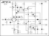
100W at 4 ohmsMr. Apex,
For the BX100 what power levels could be expected?
Thanks,
Regards
You can try with this one...
Regards
Copy that Mr. Mile....
Regards,
Yes borys, you can use j-fet input, put some base stopers at o/p transistors, reduce compensation in vas and put small compensation in driver stage. Then You should have SR around 40-50V/us and good THD results at high range.
Reduce VAS stage bias to 7mA (no need heatsink) and increase bias for driver stage to aprox 15-20mA (should swing in A class). There should be no overshoot and amp remain perfect stable.
Basicly it should look like this.
Regards
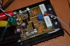
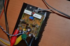
This is my AX-11 base on borys layout. PCB is very small
and working crystal clear, dead silent and no power on thump... nice amp..Attachments
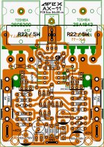
ax11
where we can find these pcb?
nice pcb can you share the pcb layout?
where we can find these pcb?
wiljj78
Nice work. I am running it at +/-45V no bother. You can try j-fets at input - just solder them, no need to do any modyfication.
By changing the compensation caps in vas and driver stage You can make amp slower or faster and make a listening tests to your preferences (SR from 10 to 45V/us).
Nice work. I am running it at +/-45V no bother. You can try j-fets at input - just solder them, no need to do any modyfication.
By changing the compensation caps in vas and driver stage You can make amp slower or faster and make a listening tests to your preferences (SR from 10 to 45V/us).
wiljj78
Nice work. I am running it at +/-45V no bother. You can try j-fets at input - just solder them, no need to do any modyfication.
By changing the compensation caps in vas and driver stage You can make amp slower or faster and make a listening tests to your preferences (SR from 10 to 45V/us).
borys,
Is bigger the number, slower the sound or the other way round ?
Thanks
Albert
borys,
Is bigger the number, slower the sound or the other way round ?
Thanks
Albert
The bigger the number the slower the amp. Bellow example.
Both signals are 20kHz square, slower one uses 100pF main compensation at the drivers, the faster one uses 33pF compensation. Amp is perfectly stable with capactive load, it uses miller caps in vas stage too to keep it stable.
Attachments
Last edited:
wiljj78
Nice work. I am running it at +/-45V no bother. You can try j-fets at input - just solder them, no need to do any modyfication.
By changing the compensation caps in vas and driver stage You can make amp slower or faster and make a listening tests to your preferences (SR from 10 to 45V/us).
Noted and many thanks borys...
100W at 4 ohms
Regards
I think it would probably get close to the 100W at 8 ohms as well. As long as the 45V rails are still close to 45V at full power. The RMS voltage would run close to 28V, which is about 100W/8ohms.
This is an interesting little amp, because we can use some left over 2N3773, as many must still be lying around in some old stock. As is the case for me, I have dozens of those old ones, never used.
The only thing that kind of bothers me is the BC546/556, which have a Vceo of 65V, so I'm wondering what those input diffs are subjected to...
- Home
- Amplifiers
- Solid State
- 100W Ultimate Fidelity Amplifier