AX-20 PROBLEM
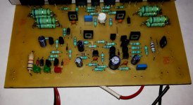
Hi friend, I assembled AX-20 amp I have attached pic. Problem with this amp is, there is no connection between Q9-Q18 and Q8-Q17. I already fixed. But that giving just big hummm with little audio so please help me whats error in this
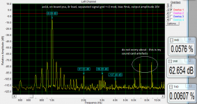
I connected amp in series with 10Ω resistance, when nothing seems to burn I put fuse and tried to adjust bias but was not able to, even winding trim-pot to full. Amp was playing music but with crossover distortion at low volume.
Hi friend, I assembled AX-20 amp I have attached pic. Problem with this amp is, there is no connection between Q9-Q18 and Q8-Q17. I already fixed. But that giving just big hummm with little audio so please help me whats error in this
Attachments
Last edited:
Thanks
Thanks for upload it in pdf format.
When you use the 2SC5200 and its complement, what package you use on sprint?
maybe this will help:
Thanks for upload it in pdf format.
When you use the 2SC5200 and its complement, what package you use on sprint?
Last edited:
Hi Rey.
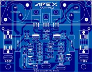
If you use this pcb on +/-50V, replace MPSA92 with BF872, BF762 or 472.
Because on that voltage and 200mW dissipation, MPSA92 will be so hot. Or use something like this:
Hi,
Thanks for the suggestion I'm just back at this thread.
Rey
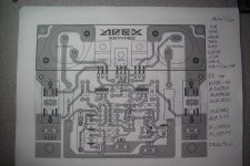
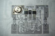
Hey Willy not sure if you are around, I have been checking your AX-11 -MK2 and is a nice design I try to print out the images you left but my printer does not give and exact size and is complicated to set , so I just copy your design and printed to the correct size is worth to try at least I have must of the parts to put it together, the images you see of the print out with the rusted old TO-3 transistors I just placed there to see if I have the correct size print out and yes is correct  ok buddy keep your good work I'm going to check the components that I need online good day bro.
Regards
Vargas
ok buddy keep your good work I'm going to check the components that I need online good day bro. Regards
Vargas
Attachments

Last edited:
Hey Willy not sure if you are around, I have been checking your AX-11 -MK2 and is a nice design I try to print out the images you left but my printer does not give and exact size and is complicated to set , so I just copy your design and printed to the correct size is worth to try at least I have must of the parts to put it together, the images you see of the print out with the rusted old TO-3 transistors I just placed there to see if I have the correct size print out and yes is correct
Regards
Vargas
Replace 3k3 with 2k2 or bias will be 600mA
Thanks for upload it in pdf format.
When you use the 2SC5200 and its complement, what package you use on sprint?
try this one:
Attachments
Hey Willy not sure if you are around, I have been checking your AX-11 -MK2 and is a nice design I try to print out the images you left but my printer does not give and exact size and is complicated to set , so I just copy your design and printed to the correct size is worth to try at least I have must of the parts to put it together, the images you see of the print out with the rusted old TO-3 transistors I just placed there to see if I have the correct size print out and yes is correct
Regards
Vargas
Hello Juan,
I'm glad you like it! and your layout look very nice too...
Now i'm going to upgrade this AX-11 into HX-11 and i will build that project soon, but as of now a bit busy at work so not have enough time for layout but definitely will finish that very soon.
Well done and good luck buddy....
Regards,
Willy
thanks
your software does not recognize my libraries, but like many thanks for your answer.
try this one:
your software does not recognize my libraries, but like many thanks for your answer.
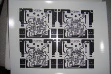
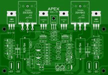
I misspell your name on the layout sorry about that my man here:
Regards
Vargas
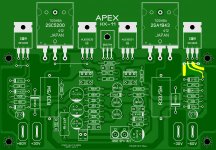
That's awesome bro.... Here's my HX-11 too just for fun...
Regards,
Willy
Attachments
That's awesome bro.... Here's my HX-11 too just for fun...
Regards,
Willy
Nice work.
Regards
That's awesome bro.... Here's my HX-11 too just for fun...
Regards,
Willy
Amazing job Willy
very neat ! ahaaaa .... I see you are using half moon for the caps really good polarity indicator for the electrolytic caps nice !Regards
Juan
Last edited:
your software does not recognize my libraries, but like many thanks for your answer.
send me your e-mail to private messages and i will send you my whole macros library as zip file. when you receive it,open zip extract and rename the MACROS folder and than use "cut" option and move it to C/Program files/Sprint50 folder. than open Sprint program and at right side under "M" you should have that aditional renamed macros folder,along with all you allready have. that way you will have your old macros files and new that you will receive.
That's awesome bro.... Here's my HX-11 too just for fun...
Regards,
Willy
wiljj my friend,at schematics at "negative side" of amplifier 15V zener is between G and S,D is directly connected to higher negative voltage. i'd say that you mixed up S and D connections,sorry if im wrong but please re-check by schemtics... otherwise,it looks great as all your pcb's
- Home
- Amplifiers
- Solid State
- 100W Ultimate Fidelity Amplifier