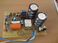
You don't need to use this LED VU pcb for Hi-Fi amp,What pcb's are used in your Ultimate Fidelity Amp ? It shows 2 for the amp, 1 for the psu and another ? That is very close to what I'm looking to build. Please list pcb's used ! Thank-you
Regards
Attachments
@ mihailo
In thread http://www.diyaudio.com/forums/solid-state/164208-500w-pa-amplifier-limiter-36.html I see yours pcb for A100, I like hear your comment here about sound and comparation betwin A100 and B500 when you finish A100,
Regards
In thread http://www.diyaudio.com/forums/solid-state/164208-500w-pa-amplifier-limiter-36.html I see yours pcb for A100, I like hear your comment here about sound and comparation betwin A100 and B500 when you finish A100,
Regards
Apex I have finished one channel, and my multimeter is showing 14.6V DC on output. Transistors were new, I have buy them today.
Just now saw your post about polarity of diode 1N4148, and reverse polarity but still I have 14V on output.
Can you help me to check are BDW trans. ok?
Don't know how to measure them, are they different in measuring from standard NPN,PNP?
Don't have much experience in electronics. I am student of Mechanical faculty University 3rd year, we learn only basic electronics.
You must connect input GND to PSU GND with separate wire (input GND and power GND are not conected on pcb), or use 10R in paralel with 100nF for test,Apex I have finished one channel, and my multimeter is showing 14.6V DC on output. Transistors were new, I have buy them today.
Just now saw your post about polarity of diode 1N4148, and reverse polarity but still I have 14V on output.
Can you help me to check are BDW trans. ok?
Don't know how to measure them, are they different in measuring from standard NPN,PNP?
Don't have much experience in electronics. I am student of Mechanical faculty University 3rd year, we learn only basic electronics.
Regards
Attachments
Last edited:
Yes, but many TO220 drivers can be use for AX14 like 2SA1306/2SC3298 or similar. For BIAS adjust put 10R resistors instead fuses and set 500mV on them,It is hard for me to get 2SC4793 and 2SA1837 . Are MJE15033 and MJE15032 good substitutions?
Regards
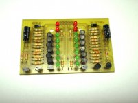
I will post in threadapex, can you post the board layout for the led vu meter?
http://www.diyaudio.com/forums/solid-state/167363-mic-line-eq-preamps-11.html
Regards
- Home
- Amplifiers
- Solid State
- 100W Ultimate Fidelity Amplifier