G.Kleinschmidt said:
Since this fixed the instability problem, try reducing the OL gain a better way.
Put the VAS buffer and current mirror transistors back in circuit and add a pair of 220 ohm emitter degeneration resistors to your LTP.
Miller compensation in this type of topology can be prone to trouble if the gm of the LTP is too high (it can't get rid of enough gain).
Using an MJE15030 with a Cob approaching the value of the external miller comp cap wouldn't help things either.
Hi Glen,
I tried 100 ohm degeneration resistors first, then 220 ohm. The 220 ohm made a slight difference, and told me my suspicions (about the OL gain) were correct. Pulling the mirror - further tiny increase in stability, but when I pulled the EF, that made the real difference.
I knew the EF acts as a buffer for the Cob of the VAS, but I considered the options: This amp MUST run stable, it can't be prone to oscillation, there's too much power involved. I don't want a Chernobyl on my hands.

Besides, this is a temporary fix, I have some better high voltage VAS drivers on order: 2SA0914. These have a low Cob (5pF).
I will use the MJE for debugging until I get these.
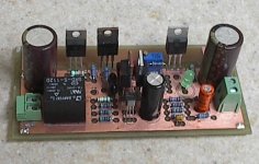
I have etched and stuffed the new board. Hopefully, this time it runs stable. I feel more confident about it this time (spider sense is tingling).
Attachments
MJL21193 said:
Hi Glen,
I tried 100 ohm degeneration resistors first, then 220 ohm. The 220 ohm made a slight difference, and told me my suspicions (about the OL gain) were correct. Pulling the mirror - further tiny increase in stability, but when I pulled the EF, that made the real difference.
I knew the EF acts as a buffer for the Cob of the VAS, but I considered the options: This amp MUST run stable, it can't be prone to oscillation, there's too much power involved. I don't want a Chernobyl on my hands.
Besides, this is a temporary fix, I have some better high voltage VAS drivers on order: 2SA0914. These have a low Cob (5pF).
I will use the MJE for debugging until I get these.
I have etched and stuffed the new board. Hopefully, this time it runs stable. I feel more confident about it this time (spider sense is tingling).
OK, the new board is looking good and has a very good probability of sucess
")
It is a pity that you didn't have the better transistors at hand for the VAS though, as the previous version may (and should) have been stable with them.
A big trannie like the MJE150XX for a VAS is waayyyy too slow in this position and it adds too much phase shift to the loop.
If you combine this with a huge output stage that adds a big capacitive load to the drivers, the overall phase shift could conceivably become difficult to manage.
That might be why you didn't get away with it this time.
MJL21193 said:I have decided to take drastic measures, and go back to the drawing board (sim in this case) and redesign to simplify the circuit a bit. Eliminate the current mirror on the LTP and the EF on the VAS. These are good to reduce distortion, but it's not a major concern for a subwoofer amp anyway.
Hi MJL21193,
When you eliminate the current mirror from the LTP, R1 should not be the same value as R2. Usually R2 is eliminated altogether. So you reduce the component count and decrease distortion.
I many books, R1 and R2 are included only because it is usually an example of a TLP with the most distortion, and therfore, it makes the current mirror TLP example look even more superior.
regards
G.Kleinschmidt said:
A big trannie like the MJE150XX for a VAS is waayyyy too slow in this position and it adds too much phase shift to the loop.
If you combine this with a huge output stage that adds a big capacitive load to the drivers, the overall phase shift could conceivably become difficult to manage.
That might be why you didn't get away with it this time.
Certainly not the ideal VAS with an ft of 30MHz, but consider that Rod Elliot used it in his P68 (the inspiration for this amp). My old version ran well, with no signs of instability. Sound quality is hard to judge in a <80Hz application, barring clipping.
The new VAS drivers are not overly fast either at 70MHz. They do have the advantage of the low Cob, and my main use for these would be for pre-drivers in a symmetrical plan I'm brewing up (no, I can't stop now
). I can spare one here though, as I'm not running the VAS too hot.Greg Erskine said:
Hi MJL21193,
When you eliminate the current mirror from the LTP, R1 should not be the same value as R2. Usually R2 is eliminated altogether. So you reduce the component count and decrease distortion.
I many books, R1 and R2 are included only because it is usually an example of a TLP with the most distortion, and therfore, it makes the current mirror TLP example look even more superior.
regards
Hi Greg,
How do you like my new distraction? Cheaper than even the cheapest women.
I simmed it both ways, with or without R2, and didn't find a significant difference. I'm seeing 0.088% THD at 493 watts into 4 ohm at 30Hz, which is better than adequate for this amp. I really haven't been paying much attention to the THD of this amp, as it's not as important as stability (I think).
Now, as for the values, I don't know if they are optimal. Wg-ski above, suggested the drop across these is too high at ~750mV, but again I defer to the sim and it shows the output will stick to the negative rail at any value less than 470 ohms. Erring on the side of caution, I look at Rod's P68 again and see he has used 560 ohms here.
I have the board ready to run, just need to drill some new holes in the heatsink to mount it. I'll then take it for a test drive.
One thing that concerns me, and that I really should have addressed earlier, is that the Vbe transistor will monitor temperature on one side of the heatsink only. Maybe a bit over cautious, but maybe I should rig a diode string to "watch" the other side too?
MJL21193 said:
Certainly not the ideal VAS with an ft of 30MHz, but consider that Rod Elliot used it in his P68 (the inspiration for this amp). My old version ran well, with no signs of instability. Sound quality is hard to judge in a <80Hz application, barring clipping.
The new VAS drivers are not overly fast either at 70MHz. They do have the advantage of the low Cob, and my main use for these would be for pre-drivers in a symmetrical plan I'm brewing up (no, I can't stop now
Forget about fT. That is a figure related to the base-emitter capacitance, which of lesser concern in a common emitter amplifier (which is what a VAS stage is) than is Cob.
A big PNP driver transistor like the 8A MJE15031 has a collector-base capacitance that varies over the range of 60pF to 300pF with operating voltage. This is what your "Cdom" miller cap is in parallel with!
Also, I know that your older amp ran well, but just because you got away with it once doesn't guarantee it will always happen, especially in an altered or different design.
I'm not trying to pick on your here, just pointing out that using non ideal parts in critical locations because you have them at hand is likely to cause you more grief than convenience.
Cheers,
Glen
G.Kleinschmidt said:
I'm not trying to pick on your here, just pointing out that using non ideal parts in critical locations because you have them at hand is likely to cause you more grief than convenience.
Cheers,
Glen
Hi Glen,
Pick on me! I"m learning here, and I'm old school that way - beat it into my thick skull with hard lessons and other Catholic School tactics such as public humiliation and the strap. I'm not in the least sensitive about this, especially when I know next to nothing on the subject.
Better IMO to say something negative that's constructive and true, rather than remain silent and watch the rookie take his lumps on his own.
A few too many silent (at least in this thread) watchers here, ones that know the difference but can't be bothered to contribute.I invite all comments, both complementary and critical. I'd rather hear the facts than be ignored. Please, if anyone sees me doing something silly of boneheaded, jump in and say "hey Bonehead, smarten up"
So I'm going by what I read: that the ideal VAS would have low Cob and high ft. I read a lot of things though, but if it comes from you Glen, then I trust the source.
As I do more project and more learning I'm adding to my understanding of the differences between devices and I'm also acquiring these devices as I go along. It's tough to know what I'll need next though, so I substitute. Not the best approach, but I'm a "get it done" type, and don't like waiting around for parts to arrive.
There's always the next version.
MJL21193 said:
I knew the EF acts as a buffer for the Cob of the VAS, but I considered the options: This amp MUST run stable, it can't be prone to oscillation, there's too much power involved. I don't want a Chernobyl on my hands.
Besides, this is a temporary fix, I have some better high voltage VAS drivers on order: 2SA0914. These have a low Cob (5pF).
I will use the MJE for debugging until I get these.
While you're at it, try those higher fT low Cob units in the predriver stage. It may make the OPS more stable and may in fact still run right with the darlington VAS.
Removing the current mirror in the front end helps some by reducing open loop gain - but make sure you trim the load resistor to balance the current in the LTP. It will *work* with a wide range of values, but if you want to keep distortion down use the one that keeps the diff pair currents the same.
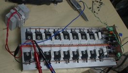
Ok, I have it running. At the +/-35V supply it's running rock steady. No sign of oscillation. This time around, I got the bias generator pretty much dead on - with the pot in the centre, I have ~20mV across the emitter resistors.
Running on this supply, I have connected my 8 ohm dummy load (the bundle of cement resistors with heatsinks on the side in the picture below). Some observations:
Output before clipping: 25.6Vpeak (18.1Vrms) into the 8 ohm load with rails supply sagging to +/-29VDC. This ~41 watts output.
Heatsink temp: An even 40*C all over in the position as shown in the picture below - fins down, no air circulation.
VAS and CCS temp: 56*C with no heatsink on either. Temp taken at the back centre of the package.
Dummy load temp: 110*C at the centre plate between the two rows of resistors. Heating the room, that is.
Attachments
It somehow slipped my mind that the 2SA1011 is a 160V device and would make a more suitable VAS. Still not ideal, but better than the MJE15031. I do the exchange and fire up the amp again. There isn't a noticeable difference in the sine wave output, but the squarewave is a little sharper, especially negative going.
The problem is with the clipping behavior, With the MJE, clipping was very clean, a little jittery on the negative going wave, but very clean overall.
The 2SA1011 on the other hand is terrible - really harsh clipping. So bad it makes the bias LED blink. Not only that, but when the signal is taken away, I have 10VDC on the output. This is only with no signal. With signal, the DC at the output is <2mV.
Although I used this for the VAS in the Patchwork project, I never could properly sim this transistor, as there's no model (that I can find) for it. In that case, I used another modified model from a device that had similar specs (can't remember the specific one).
So, what's going on?
Hi John
Sorry this suggestion is a little late!
One option for the output stage would be to use straight triple common-collector output halves. I agree with others in a different thread that the triple NPN/PNP configuration seems to be the best for high power.
For example, if you had MJE15033 drivers, then as these are not enough to drive 8 MJL21194's perhaps rather than having MJ21193 driving the output devices, a parallel arrangement of MJE15033's would be needed.
IN this suggestion you would have:
upper output: MJE15033 driver (NPN)- then four MJE15033's with each MJ15033 driving two MJL21194's.
lower output: complementary MJE15032-4x(MJE15032-2xMJL21193)
The bias stabiliser, and total of 10 drivers and 8 outputs would be needed to be mounted on the output heatsink.
Anyone think this would be a useful arrangement?
cheers
John
MJL21193 said:The 2SA1011 on the other hand is terrible - really harsh clipping. So bad it makes the bias LED blink. Not only that, but when the signal is taken away, I have 10VDC on the output. This is only with no signal. With signal, the DC at the output is <2mV.
Although I used this for the VAS in the Patchwork project, I never could properly sim this transistor, as there's no model (that I can find) for it. In that case, I used another modified model from a device that had similar specs (can't remember the specific one).
So, what's going on?
Put a base stopper on the CCS for the VAS if you use a common reference for it and the one for th LTP. They'll talk to one another when you clip if you don't include the resistor.
Never had a problem with the 1011 - or a model for that matter. I just wish I had a good source for the 1011/2344 pairs again.
john_ellis said:Hi John
Sorry this suggestion is a little late!
One option for the output stage would be to use straight triple common-collector output halves. I agree with others in a different thread that the triple NPN/PNP configuration seems to be the best for high power.
For example, if you had MJE15033 drivers, then as these are not enough to drive 8 MJL21194's perhaps rather than having MJ21193 driving the output devices, a parallel arrangement of MJE15033's would be needed.
IN this suggestion you would have:
upper output: MJE15033 driver (NPN)- then four MJE15033's with each MJ15033 driving two MJL21194's.
lower output: complementary MJE15032-4x(MJE15032-2xMJL21193)
The bias stabiliser, and total of 10 drivers and 8 outputs would be needed to be mounted on the output heatsink.
Anyone think this would be a useful arrangement?
cheers
John
That's an awful lot of devices for what is already a wiring nightmare. A straight triple darlington with a single MJE or 2SC TO-220 driving a single MJL or 2SC5200 which drives the parallel bank of MJLs will give the least amount of trouble. I'm kinda surprised he got the CFP drivers to work at all into that much capacitance.
john_ellis said:Hi John
Sorry this suggestion is a little late!
One option for the output stage would be to use straight triple common-collector output halves.
Hi John,
Always better late than never. I have been trying to wrap my head around the scheme you have outlined. I even spent some time working it on the simulator. It would be nice if you could illustrate in a sketch what you mean. Even if I didn't use it, I could have it for future reference.
wg_ski said:
Put a base stopper on the CCS for the VAS if you use a common reference for it and the one for th LTP. They'll talk to one another when you clip if you don't include the resistor.
Never had a problem with the 1011 - or a model for that matter. I just wish I had a good source for the 1011/2344 pairs again.
Hi wg_ski,
I'm hung up on what the difference could be between the MJE which works well and clips beautifully, and the the 2SA1011, which works better with a signal, but clips like a pickax and produces the DC at the output with no signal.
BTW, Ampslab has the 1011/2344, that's where I got em.
john_ellis said:HI John
I would always recommend separate CCS for input and VAS stages...
I don't think a base stopper is the right approach because this slows down the response of the VAS CCS.
cheers
John
They are separate, just share the common bias (LED1). Do you mean I should separate bias the VAS CCS?
MJL21193 said:
Hi wg_ski,
I'm hung up on what the difference could be between the MJE which works well and clips beautifully, and the the 2SA1011, which works better with a signal, but clips like a pickax and produces the DC at the output with no signal.
I think the problem may not be with the 2SA1011, but the CFP driver. As wg_ski has mentioned, getting that stable into so much load is an achievement.
With the 2SA1011 the VAS will have a lower high frequency output impedance. Cdom provides a tight local negative feedback around the loop, which highly linearizes (if that is a word) the VAS and reduces its output impedance.
The higher the VAS hfe out to HF, the higher the VAS input impedance and the greater the amount of local negative feedback. This is why D. Self adds the emitter follower buffer to the VAS – it greatly raises the VAS input impedance and increases the local NFB.
So, the 2SA1011 VAS could possibly be driving your CFP’s with a low enough HF impedance to cause trouble.
Another possibility is that dominant pole of the miller compensation is moved too far out with the 2SA1011 instead of the MJE.
Remember that you Cdom cap is in parallel with the (comparatively) huge collector-base capacitance of the MJE, so with the 2SA1011 substituted, you have less effective miller capacitance, and a higher frequency Cdom roll-off.
If this is the case, the amp should be stable with the 2SA1011 if you add and extra 50 or 100pF to the miller cap.
Cheers,
Glen
G.Kleinschmidt said:
I think the problem may not be with the 2SA1011, but the CFP driver. As wg_ski has mentioned, getting that stable into so much load is an achievement.
If this is the case, the amp should be stable with the 2SA1011 if you add and extra 50 or 100pF to the miller cap.
Is there a possibility that we are not giving Rod Elliot enough credit here, and that he burned through these same problems during his initial design and settled on the MJE as VAS because it simply worked well and provided the stability required? It is largely his design that this is based on, especially the CFP output configuration and his use of an MJE15033 as VAS.
Would increasing the Miller cap defeat the purpose of the low Cob VAS?
Could the clipping problem be attributed to the low rail voltage and current availability, since this output stage does have a big demand?
Clipping behavior aside, the most pressing problem I have now is the appearance of DC at the output when the signal is taken away. If I turn off the FG without unplugging the input cable to the amp it's fine, normal DC offset. But if I unplug the cable, I have 10-20VDC at the output. What is the problem here?
Hi,
i think the capacitance of the VAS changes as Vce changes.
A low capacitance transistor//ideal cap is better than a high capacitance transistor.
I would go further and remove the 1011 which is a driver type and substitute a true low capacitance transistor for the VAS. Then EF it to generate the current required for the next stage.
Project Stability!!!
With all our help here, we can help get this man's amp stable!
Question......
Why would an TO-220 MJE-based VAS be too slow? 30 or 35Mhz transistors??? Rod uses them in his amps just fine, and I've used them myself because they run cooler than TO-126 at high voltages.
I used MJE 15035 on a heatsink for a 17mA VAS to drive a CFP and it works fine, and since it has a good power rating, and a heatsink with no insulator, and it doesn't get hot, just slightly warm @ +/-75V
Although, my design just used only one driver pair to drive 5 pairs of MJL4281/4302.
..............................................................
*Now I notice your zobel of 0.1uf/4.7. Have you tried 0.22uf? I had slight stability issues myself with that zobel until going to a 0.22uf cap instead. Maybe even try 0.47? Also, since you have 8 output pairs, multiple drivers, and a large output stage. I would assume a better zobel would keep it under control better.
I doubt it would hurt, because any treble within the zobels range just dissipates as heat in the 4.7resistor anyway, just use a large zobel resistor just in case, and also this is a BASS amp, so HF performance isn't critical, but keeping out the HF noise IS.
.........................................................
I was comparing your design to Rod's P3A and P68.........
Rod's design in BOTH P3A and P68 use a 100pf cap on the b-e junction of the drivers. Your amp has no such compensation. I did this myself but used 1000pf (102) and it worked fine, even plays great with treble under testing. You may want to try this to improve stability.
.........................................................
Also, have you tried smaller than 500K for an input resistor? Maybe 100K or 47K instead? You did mention your amp has DC offset with NO input( or open input with nothing plugged in). Have you also tried grounding the input cap for troubleshooting to see if that offset goes away? Most amps I know make some noise with nothing on the input, or if you touch the input wire with your fingers with nothing connected
- Status
- This old topic is closed. If you want to reopen this topic, contact a moderator using the "Report Post" button.
- Home
- Amplifiers
- Solid State
- 1000 Watt Sub Amp: Design / Build