Re: Re: Re: Re: 1000 Watt Sub Amp: Design / Build
This only applies to a purely resistive load.
You must consider a reactive load.
The 45degree phase angle roughly doubles the IV across the devices and 60degree phase angle roughly trebles the IV across the devices. That would bring your two pair up to 4pair or 6pair depending on what phase angle you want as your limiting worst case condition.
In addition you must de-rate the device dissipation to take account of the device case temperature (Tc). This brings us to at least 8pairs to drive 1000W into 2ohms reliably in most domestic situations.
nigelwright7557 said:
I worked out what I could use from the max dissipation in the MOSFETS. They are 150watts.
Given they are only on for half the time then this gives 300watts per half cycle.
The power dissipation is a little odd when you first look at it because it has a max at half the voltage rail. Clearly at 0V there is no current and at 48v (my amp) iti s another minimum as virtually no volts across the MOSFET.
I reckon at worst case I get 144WRMS into the MOSFET but this has to be divided by 2 as each MOSFET only works on a half cycle.
I reckon I can get 1000WRMS if I pair up the MOSFETS but this would be into 2 ohms and not the current 4ohms I use.
In practice I must admit to be using a massive heatsink which is fan assisted. I ran the power amp with a music signal to just below clipping for half an hour and the MOSFETS get slightly too hot to touch so maybe around 50-60 degrees C and the heatsink stays cool.
The only things I dont like about the MOSFETS is the gate voltage needs to be higher than a bipolar solution. This means I need a higher voltage power rails for the MOSFET solution.
This only applies to a purely resistive load.
You must consider a reactive load.
The 45degree phase angle roughly doubles the IV across the devices and 60degree phase angle roughly trebles the IV across the devices. That would bring your two pair up to 4pair or 6pair depending on what phase angle you want as your limiting worst case condition.
In addition you must de-rate the device dissipation to take account of the device case temperature (Tc). This brings us to at least 8pairs to drive 1000W into 2ohms reliably in most domestic situations.
I hope everyone around here is aware of the liberties they take with SOA on modern pro amps these days. +/-70V class AB will likely use 4 pairs of jap devices or 3 pairs of MJLs. And they advertise 2 ohms.
8 pairs will be just fine. Respect the 100mS temperature derated SOA and you'll be further ahead than any amp you buy at a store.
8 pairs will be just fine. Respect the 100mS temperature derated SOA and you'll be further ahead than any amp you buy at a store.
wg_ski said:
8 pairs will be just fine. Respect the 100mS temperature derated SOA and you'll be further ahead than any amp you buy at a store.
I wanted this to be a "fanatics" (see forum sub-title) amp from top to bottom, if not completely over the top, then very close to it. Having less than 8 pairs of outputs would be unacceptable. Doing the bare minimum is not what I was shooting for.
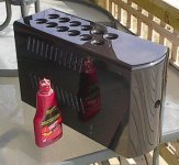
More work on the case over the weekend. We had good weather here both days, and I had the opportunity to paint the finish on the case. Despite a few problems (like a huge run down the front where my dog tangled himself in the air hose and jerked the sprayer in my hand), it turned out very well. The more I use the waterbased urethane paint, the more I like it. Simply amazing paint for doing this work.
Many coats - I used ~1/2 litre undiluted paint. I increased the air pressure to the sprayer to 80lbs and kept the paint a little thicker than I normally would have and got a very smooth spray finish. Virtually no orange peel. This made it a lot easier to colour sand.
Here's a picture of it after the first polish. It needs to be polished once more and waxed before I call it done.
Lookin' pretty sharp already.
")
Attachments


Thank you very much dudaindc,
The "guts" are getting there. I'm decidedly slower and less experienced with the electrical side as opposed to the mechanical - I can build stuff like that case with my eyes closed practically. Sorry for boasting.
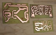
As for the guts, I etched 3 boards tonight. The main power relay board, the soft start board and the power amp front end board.
Depending on my work load this week (looks light), I could probably test fire this amp on lower rail voltage in a couple of days. With the amp front end board populated and connected to the output stage, there will be no reasons not to try it.
I must say that I'm hooked on the laser transfer method for PCB's. I went to Staples and got the correct photo paper as recommended by Tom Gootee, and it makes a huge difference. I have used magazine paper which works, but not as well as the photo paper.
The etchant I use is Tom's formula too - peroxide and muriatic acid. This is fairly cost effective, the only problem being that I can't find peroxide in bigger than 300ml bottles (they cost $2.59 each). Kinda eating up the cost savings with the peroxide alone.
Listen to me whine! Here's the 3 boards. Ready for laser transfer silkscreen.
The "guts" are getting there. I'm decidedly slower and less experienced with the electrical side as opposed to the mechanical - I can build stuff like that case with my eyes closed practically. Sorry for boasting.
As for the guts, I etched 3 boards tonight. The main power relay board, the soft start board and the power amp front end board.
Depending on my work load this week (looks light), I could probably test fire this amp on lower rail voltage in a couple of days. With the amp front end board populated and connected to the output stage, there will be no reasons not to try it.
I must say that I'm hooked on the laser transfer method for PCB's. I went to Staples and got the correct photo paper as recommended by Tom Gootee, and it makes a huge difference. I have used magazine paper which works, but not as well as the photo paper.
The etchant I use is Tom's formula too - peroxide and muriatic acid. This is fairly cost effective, the only problem being that I can't find peroxide in bigger than 300ml bottles (they cost $2.59 each). Kinda eating up the cost savings with the peroxide alone.
Listen to me whine! Here's the 3 boards. Ready for laser transfer silkscreen.
Attachments
Well, I put the pedal to the metal last night and finished populating the amp board. I found that I could have made it a bit bigger - it's pretty tight, but everything fit ok. connected it to the output stage and gave it a try with +/-9V, low current power supply - output is at negative rail voltage. Looking things over, I see no bridges or other obvious problems. Check to make sure all of the transistors are oriented the correct way. I had the VAS backwards. Always a good idea to start off with low voltage to check for these stupid mistakes. No harm done.
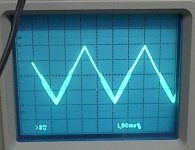
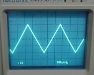
Flip the VAS around and everything looks good, 4-5mVDC offset, no smoke. Hook up the scope and FG and wow, seismic activity! Looks like oscillation. I rig up a Zobel and that greatly improves things, but It still has it bad negative going. It's clear to see in the pic below.
How am I going to make this amp run stable? Given the special circumstances involved (large output stage on the heatsinks that are conducting rail voltage)? This is still at +/-9VDC supply, I need to tame the instability before I go higher.
Attachments
MJL21193 said:Hi Nigel,
Do you mean the Miller cap? I'm using 100pF here. High frequency response is not a concern, this being a subwoofer amp, so maybe I'll try a higher value.
Thanks.
I think I used 220pf but I have darlington VAS.
MJL21193 said:How am I going to make this amp run stable? Given the special circumstances involved (large output stage on the heatsinks that are conducting rail voltage)? This is still at +/-9VDC supply, I need to tame the instability before I go higher.
You have insufficient current in the VAS. IIRC, you use a boot strapped collector resistor, and Idq will go way down with only +/-9V. Some amps will squeal audibly as the rails drop that low. Raise it to +/-30 with a lightbulb limiter and I bet it goes away. Once you've got the gross problems ironed out you can do that.
wg_ski said:
You have insufficient current in the VAS. IIRC, you use a boot strapped collector resistor, and Idq will go way down with only +/-9V. Some amps will squeal audibly as the rails drop that low. Raise it to +/-30 with a lightbulb limiter and I bet it goes away. Once you've got the gross problems ironed out you can do that.
I was sort of thinking along those same lines - that current supply was too low. I will try it on my +/-35V supply and see how it looks.
I did try a higher Miller cap (paralleled another 100pF) and it made a difference, but didn't completely clear it up. That got me thinking about the high open loop gain of the EF VAS, and how increasing the emitter resistors in the LTP would reduce this. In my haste to get it done last night, I used 39 ohm resistors instead of 56 ohm. On another project it was recommended that these be increased to 100 ohms or more.
Something else to check.
At +/-9V rails your amp would never work well.
Use the whole +/-70V rails! Don't forget to apply a 60W light bulb in series with the mains tranformer's primary coil!
Don't afraid, the bulb protects your amp in case of any short circuit etc.
If an amp is designed for +/70V rails, then use +/-70V rails. And not +/-9V! In my opinion the +/-35V as suggested here is low too!
Use the whole +/-70V rails! Don't forget to apply a 60W light bulb in series with the mains tranformer's primary coil!
Don't afraid, the bulb protects your amp in case of any short circuit etc.
If an amp is designed for +/70V rails, then use +/-70V rails.
And not +/-9V! In my opinion the +/-35V as suggested here is low too!Andy L. Francis said:At +/-9V rails your amp would never work well.
Use the whole +/-70V rails! Don't forget to apply a 60W light bulb in series with the mains tranformer's primary coil!
Don't afraid, the bulb protects your amp in case of any short circuit etc.
If an amp is designed for +/70V rails, then use +/-70V rails.
Hi Andy,
The purpose of the +/-9V supply is to locate any of my stupid mistakes (like installing the VAS backwards). Once I see it will actually run, I switch to a higher voltage. In this case, unlike other projects I've done, I noticed instability. It really should run stable at the 9 volt supply.
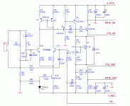
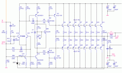
I did go to the +/-35V supply and had the same instability. I'll post the schematic again here for reference. I'm having a real problem with adjusting the bias - with a tiny turn to the multiturn pot, it jumps from 0.1mV to ~35mV. I experienced this before on my Patchwork amp, and overcame the problem, but I can't remember exactly what I did to solve it.
I have tried different resistor values in the Vbe multiplier, different (higher) resistors for the bootstrap. Nothing has worked so far.
Attachments
MJL21193 said:
I did go to the +/-35V supply and had the same instability. I'll post the schematic again here for reference. I'm having a real problem with adjusting the bias - with a tiny turn to the multiturn pot, it jumps from 0.1mV to ~35mV. I experienced this before on my Patchwork amp, and overcame the problem, but I can't remember exactly what I did to solve it.
I have tried different resistor values in the Vbe multiplier, different (higher) resistors for the bootstrap. Nothing has worked so far.
Things I would try in this order:
Insure that your CFP drivers are physically as close together as possible. Any parasitics get amplified and phase margin can disappear. You have half on the PCB and the other half on the HS, and wires over a couple inches will make it so that it will never work at all.
Reduce C15 (use fractional uF). I've seen too large a cap here cause the hysteresis you're observing in the bias, as well as switchoff problems.
Degenerate Q4 slightly. Experiment with an emitter resistor.
Reduce R1 and R2. You want about 50mV drop, no more is needed.
Try the amp without a zobel. Don't ask why but sometimes it works
wg_ski said:
Things I would try in this order:
Insure that your CFP drivers are physically as close together as possible. Any parasitics get amplified and phase margin can disappear. You have half on the PCB and the other half on the HS, and wires over a couple inches will make it so that it will never work at all.
Reduce C15 (use fractional uF). I've seen too large a cap here cause the hysteresis you're observing in the bias, as well as switchoff problems.
Degenerate Q4 slightly. Experiment with an emitter resistor.
Reduce R1 and R2. You want about 50mV drop, no more is needed.
Try the amp without a zobel. Don't ask why but sometimes it works
Thanks for the suggestions. I had already tried a few of these with no success. The others I just finished and still no improvement. I even went to the trouble of removing the Vbe multiplier components and using a diode string instead. There is still a lingering instability.
I have decided to take drastic measures, and go back to the drawing board (sim in this case) and redesign to simplify the circuit a bit. Eliminate the current mirror on the LTP and the EF on the VAS. These are good to reduce distortion, but it's not a major concern for a subwoofer amp anyway.
I'll be back soon with another schematic. I have some reading to do: D. Self, R. Slone, B. Duncan.
desperate times
call for desperate measures. But before you go unhooking things that are not likely to be hurting anything (like the darlington vas), remember that CFPs can be troublesome and what causes the oscillation may be parasitics that are unknown and not in the spice model. They work well with high fT small dies that don't have much SOA, but go too big or spread everything out and they get stoopid. You've pretty much elimianted everything else already. For grins, try disconnecting the collectors of Q6 and Q27, and short R4 and R12 temporarily. That will force it to a standard double emitter follower and if it's stable that way, just reconfigure to a standard triple and you're problems are over.
call for desperate measures. But before you go unhooking things that are not likely to be hurting anything (like the darlington vas), remember that CFPs can be troublesome and what causes the oscillation may be parasitics that are unknown and not in the spice model. They work well with high fT small dies that don't have much SOA, but go too big or spread everything out and they get stoopid. You've pretty much elimianted everything else already. For grins, try disconnecting the collectors of Q6 and Q27, and short R4 and R12 temporarily. That will force it to a standard double emitter follower and if it's stable that way, just reconfigure to a standard triple and you're problems are over.
Re: desperate times
Hi wg_ski,
To do that, I'd need to replace the 3.3 ohm emitter resistors, or the drivers may burn out.
I heard that the CFP has some stability problems, but that is the configuration of the ESP amp that I first built, wired point to point - a real mess but it works flawlessly. I really thought the problem stemmed from somewhere else, and removal of the EF on the VAS and the current mirror pretty much proves that. The amp runs stable now.
So, with that in mind, another kick at the cat. I have revised the circuit to include the changes above plus I have substituted the bias generator for the one from my Patchwork amp. This uses a different transistor with a higher Vbe than the BD139.
I have also switched to a current source instead of the bootstrap.
I'll be working this up on a piece of perf board this time, rather than go to the trouble of etching a board for an unproven design.
wg_ski said:
For grins, try disconnecting the collectors of Q6 and Q27, and short R4 and R12 temporarily. That will force it to a standard double emitter follower and if it's stable that way, just reconfigure to a standard triple and you're problems are over.
Hi wg_ski,
To do that, I'd need to replace the 3.3 ohm emitter resistors, or the drivers may burn out.
I heard that the CFP has some stability problems, but that is the configuration of the ESP amp that I first built, wired point to point - a real mess but it works flawlessly. I really thought the problem stemmed from somewhere else, and removal of the EF on the VAS and the current mirror pretty much proves that. The amp runs stable now.
So, with that in mind, another kick at the cat. I have revised the circuit to include the changes above plus I have substituted the bias generator for the one from my Patchwork amp. This uses a different transistor with a higher Vbe than the BD139.
I have also switched to a current source instead of the bootstrap.
I'll be working this up on a piece of perf board this time, rather than go to the trouble of etching a board for an unproven design.
Attachments
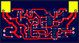
Here's the board layout for the above. I have decided to go ahead and etch it, the thought of trying to do it on perf board is too depressing.
I have made the layout a bit more spacious and I've included an input muting relay that will pull the input to ground when released. I thought it would be a good idea to do this so that the speaker switching relay will not be switching a heavy load.
I have also made a slight change to the Vbe multiplier, adding a resistor.
Attachments
Removing the VAS buffer and current mirror transistors would have the effect dramatically increasing the load on the LTP and reducing the open loop gain.
Since this fixed the instability problem, try reducing the OL gain a better way.
Put the VAS buffer and current mirror transistors back in circuit and add a pair of 220 ohm emitter degeneration resistors to your LTP.
Miller compensation in this type of topology can be prone to trouble if the gm of the LTP is too high (it can't get rid of enough gain).
Using an MJE15030 with a Cob approaching the value of the external miller comp cap wouldn't help things either.
- Status
- This old topic is closed. If you want to reopen this topic, contact a moderator using the "Report Post" button.
- Home
- Amplifiers
- Solid State
- 1000 Watt Sub Amp: Design / Build