If you want to use switchable #26/01a preamp, the target anode-cathode voltage will be below 135V.
If the anode current 3mA, the grid voltage 9V (on the filament bias resistor, so R about 36-47R), you need to stabilize B+ at about 150V.
The only disadvantage to use LL2745 with 01a, the desired source impedance (3k). The 01a has 10-11k Ri.
If the anode current 3mA, the grid voltage 9V (on the filament bias resistor, so R about 36-47R), you need to stabilize B+ at about 150V.
The only disadvantage to use LL2745 with 01a, the desired source impedance (3k). The 01a has 10-11k Ri.
PSU should be fine. You won't regret it. I've found the gyrator to be more detailed than Lundahl the interstages I tried like LL1635, LL1660. And the 01A is marvellous. Get some from the USA, like a dozen - they're a good investment. I have some dealers' names if you email me.
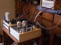
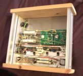
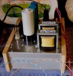
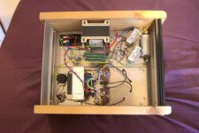
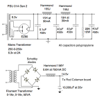
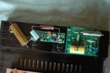
Here's some photos of a recent 01A Gen 2 build for a fellow enthusiast. It shows the 2 chassis design - signal chassis and PSU+filament supply. One photo shows the preamp feeding my 4P1L PSE output stage. I just use these 2 stages from my DAC to the Altair 10 speakers. Sorry about the slightly blurry images for a couple of photos.
Attachments
My gyrator boards arrived from Ale yesterday. I thought he hadn't soldered the SMD devices to it, but they are so small I had missed them! 
I and another builder have started a thread over on HiFiWigwam where we can throw ideas back and forth, but I suspect here is where most of the answers will come from. He has just built a 4P1L pre with PCBs he bought, but his 01A will be hardwired, like mine will.
As I need 5 inputs, the RCA sockets are going to be a major expense!
I and another builder have started a thread over on HiFiWigwam where we can throw ideas back and forth, but I suspect here is where most of the answers will come from.
He has just built a 4P1L pre with PCBs he bought, but his 01A will be hardwired, like mine will.As I need 5 inputs, the RCA sockets are going to be a major expense!
Can one of you gents tell me what size sensing resistor you are using on the Coleman regulator board for the ux201a or similar 01a tube? I'm in the process of converting my 4p1L linestage that is an OT design and filament bias to Ale's 01a gyrator design to see what all the fuss is about. I have a few Cunningham globes on the way!
TIA,
Jim
TIA,
Jim
3R9.
I use Mills MRA5, MRA12 or Welwyn W23, W24.
I'm using 4.7R with a pair of V4 regs, given that the 01A is starved. I'm just building some V7 regs - don't know if it makes a difference. I was sizing the resistor for .9V through it.
W23 and W24 are BIG! There's only about 0.25 watt going through the resistor - 3W like W21 would surely be well oversizing the resistor! Maybe a good thing if there's space.......?
MRA12 or W24 is perfectly fit near to R.C. regulator board.Maybe a good thing if there's space.......?
Space is important thing, especially if the the resistor length is about 13 cm (Duelund graphite).
))This will be the next step of my (daily #26) preamp modification.....
Attachments
Thanks all for answering my resistor question for the 01a filaments!
I understand the criticality of the coupling cap (C2) on the output of the gyrator board but how critical is the quality of C1? I bought Wimas but I have some of the tasty 0.1uF Russian teflons in my stash that I could use.
Jim
I understand the criticality of the coupling cap (C2) on the output of the gyrator board but how critical is the quality of C1? I bought Wimas but I have some of the tasty 0.1uF Russian teflons in my stash that I could use.
Jim
If you use filament biased (feeds with Rod Coleman regulator), Ale's gyrator loaded preamp, IMHO the most critical components (aside from PSUs quality):
- output coupling capacitor (I usually use V-Cap CuTF);
- "lower" FET of gyrator (the output impedance mostly depends of FET's conductance);
- type of filament bias resistor (non inductive type);
- gyrator's C1 capacitor (good polypropylene capacitor or russian for example K40Y-9) -I'm not a fan of Wima-);
- Bias resistor in Rod's regulator (I use Mills or Welwyn);
- 220nF capacitor in Rod's regulator (I use Amtrans AMCO metalized PET);
If you use filament biased (feeds with Rod Coleman regulator), Ale's gyrator loaded preamp, IMHO the most critical components (aside from PSUs quality):
- output coupling capacitor (I usually use V-Cap CuTF);
- "lower" FET of gyrator (the output impedance mostly depends of FET's conductance);
- type of filament bias resistor (non inductive type);
- gyrator's C1 capacitor (good polypropylene capacitor or russian for example K40Y-9) -I'm not a fan of Wima-);
- Bias resistor in Rod's regulator (I use Mills or Welwyn);
- 220nF capacitor in Rod's regulator (I use Amtrans AMCO metalized PET);
That's a pretty good list! I have other choices.
- "lower" FET of gyrator - haven't directly compared 2SK170 and BF862 yet. anybody done this?
- filament bias resistor - I did a shoot-out here and abandoned my Welwyn W24s and Dale surplus ones for Russian ones which were smoother.
- gyrator's C1 capacitor and output cap. Here I use FT-2 Russian teflons. Smaller in size than FT-3 so 0.1 goes neatly on the gyrator (use with 10meg resistor, not 4.7 meg), and I use 2 in parallel for the output.
- Bias resistor in Rod's regulator - Mills or Welwyn agreed or other quality ones.
- 220nF capacitor in Rod's regulator - I'll have to look at Amtrans AMCO metalled PET, thanks for the idea. Currently using vintage Siemens stacked film.
I used Hovland Musicaps in my 26, but I now have a bunch of these. I wonder if they would be any good? But when I tested them with my Chinese capacitance/ESR tester, the capacitance readings are fine but ESR comes out at around 1 ohm! (I bought them for my speaker crossovers.)- 220nF capacitor in Rod's regulator - I'll have to look at Amtrans AMCO metalled PET, thanks for the idea. Currently using vintage Siemens stacked film.

I just received some of Ale's gyrator boards with the presoldered BF862. Last night I modified my 4p1L OT coupled linestage with the gyrator boards and had difficulty getting the current below 30 ma (with 12 ohm filament resistor) Also the plate voltage is swinging too much. I'm going to throw in the towel and go ahead with modifying my breadboard to accommodate a pair of Cunningham CX-301a's because I'm afraid of frying the JFETs. So I have not got a chance to hear the 4p1l loaded with the gyrator but that will have to do for now. It's hard to imagine getting better than what I'm hearing from the 4p1l with L1660 outputs, but this is journey that never ends!
Thanks for all the help here.
Jim
Thanks for all the help here.
Jim
Hi Jim, it sounds like oscillation from what you are writing. Did you add grid and screen stoppers? The 4p1L with gyrator can easily enter into oscillation when you measure the voltages at the anode with a DVM with long leads. Try also bypassing HT supply with a 10-40uf cap plus a 100nf film cap in parallel
Jim,
If you use for 4P1L 12R and -for example- 550mA starved filament, the bias approximately -8V.
At the same B+ than IT loaded version (150-170V depends of IT primary DCR), the anode-cathode voltage at 30mA about 125V, thus anode voltage about 143V.
The mu of gyrator loaded 4P1L about 8, so anode swinging to up 150V peek at 1V input, and up to 158V peek at 2V in.
The gyrator FETs "loves" about 10-30V+ over the maximum swing peek (voltage of Rmu, and minimizing THD), so requiring B+ is -minimum- about 170-190V.
Ale's gyrator "biased" by LND150 CCS (0.4...1mA), which is generates voltage on the 220k-390k resistor (R4). The value of the resistor depends of the requiring voltage (few Volts larger than anode voltage).
The LND150 CCS also "loves" 10-30V voltage over this bias resistor, so supposed B+ is about (1mA*R4)+10...30V.
If you use 220k, the requiring voltage -for example- about 220V.
These are not complex calculations, but must be done before use another tube.
Hi Jim, it sounds like oscillation from what you are writing. Did you add grid and screen stoppers?
Hi Ale, Yes, I have a 100 ohm grid stopper and I have a 100 ohm resistor and diode between pins 2 and 3. Pin 4 is tied to pin 8. The tube is very stable with the Lundahl outputs at about 150vdc on plate and -8vdc on cathode. Filament bias of course with Coleman regulators.
And to euro21's comments - R4 on gyrator is 470 ohms with BF862 JFET per Ale's instructions. I started the test with a shunt regulator from K&K audio in front of the gyrator board but I bypassed when I thought the issue was a low B+. My B+ supply to gyrator is a well filtered 220vdc now with not regualtor. I first used 22k load resistors to set the gyrator to 169 vdc and it was very stable. When I installed the tubes, the voltage dropped and then oscillated. I measured current through the test resistor to be 30 to 33 ma so I got cold feet and quit. You guys are WAY more versed in this than me but it appears this tube is not easily controlled at lower currents with the gyrator in place at least. I was able to dial in extremely well with the shunt regulator and Lundahl 1660s.
If you experts see something I'm missing by all means let me know. I'm very comfortable troubleshooting conventional tube circuits but this one flyes over my head - but after all, I'm the wrong kind of engineer!
Jim
- Home
- Amplifiers
- Tubes / Valves
- 01A question