but the feedback loop is connected directly to the output, hence no resistor at outputI am not sure it is entirely comparable. See the (parallel?) resistance on the WHAMMYs outputs
Anyway, reduce the resistor and report back with your impressions. Curious if you think it makes a difference. It might.
Also remember that ultimately, BA2018 isn’t a headphone amplifier, it’s a linestage that can be made strong enough to drive headphones. I think it works quite nicely, but there are dedicated HPA that you may want to try if you find you need something more.
Also remember that ultimately, BA2018 isn’t a headphone amplifier, it’s a linestage that can be made strong enough to drive headphones. I think it works quite nicely, but there are dedicated HPA that you may want to try if you find you need something more.
Not finding anything for hammond BMCF transformer.
You could absolutely add a transformer to the output, it would work beautifully. Something like a quadfilar line transformer, CineMag CMOQ-4 or Jensen jt123flpch. Also a 600:600 Edcor would work very nicely indeed.
Jim - Thanks for the follow-up!
The BMCF is a Jensen transformer so...my mistake. Sorry.
Specs are here:
https://www.jensen-transformers.com/wp-content/uploads/2014/08/jt-11-bmcf.pdf
My confusion stems from using this transformer after the BA2018 gain stage. I can't imagine overdriving the transformer, but if the gain were kicked up to, say, 6 dB, at full volume with a 2V input would put nearly 4V as input to the transformer. Safe???
I gather from your Jensen suggestion that it could be safe, but will read up on that model to be sure.
That transformer is rated for full output at +27dBu!! Nice.
“What the heck is a dBu?” I hear somebody ask, and it’s just dB referenced to 0.775v - so +0dBu is 0.775v.
Ok, cool, which means that +27dBu is ( dBu = 20 log (Volts/0.775) ) = 17.34v.
Full power bandwidth at 17.34v
And the best part? dBu is an RMS measurement… so the transformer is swinging 49v peak to trough.
Thank you! This is the kind of data I was looking for.
But full power bandwidth at 17.34v...transformer swinging 49v peak to trough...am I setting up a hair-trigger BA2018 through the balanced outputs? What if I use this setup to drive, say, my ACAs in balanced mode? From what I understand they only need 4V for the coveted "full output." (I'll add a LOL because that phrase seems over-used.)
But full power bandwidth at 17.34v...transformer swinging 49v peak to trough...am I setting up a hair-trigger BA2018 through the balanced outputs? What if I use this setup to drive, say, my ACAs in balanced mode? From what I understand they only need 4V for the coveted "full output." (I'll add a LOL because that phrase seems over-used.)
I am reporting back.Anyway, reduce the resistor and report back with your impressions. Curious if you think it makes a difference. It might.
I reduced resistor R19 from 27 Ohms to 1 Ohm.
For those who haven't followed my previous posts, I'll add that I did this for the reason that I'm using the linestage as a headphone amplifier with the HifiMan Ananda, which have an impedance of 25 Ohms (or 30 Ohms as I've found in other sources).
After the change I tested the linestage loaded with a 33 Ohm resistor at an output voltage of 6Vp-p 1KHz - about 140mW - this is much higher than needed for listening - nothing overheated.
btw. After loading with a 33Ohm resistor, the output voltage dropped from 7Vp-p to 6 Vp-p, which suggests an output impedance of 5 OHm for the amplifier itself.
Now for the most important thing i.e. the sound.
Before the change something has been missing for me. The sound in comparison to my other headphone amplifier (opa627Bp+tpa6120) was worse, less engaging, less spacious, flatter - not what I expected from such a well-regarded design
After the change things got much better, the sound is full, pleasantly warm, detailed and "full of air"
At the moment I no longer think that my second amplifier is better, quite the opposite.
Or maybe I'm just imagining things....
To sum up, if you have built a circuit with a stronger output and use it with low-impedance (and high-sensitivity) headphones - I recommend trying to lower the value of resistor R19 (in both channels, of course).
Best
Marek
@bhjazz The output is going to be a fixed ratio of whatever you put on the input.
In the case of this particular transformer, the ratio is 1:1 .
So if you put 4v in, you’ll get 4v out.
You asked if the transformer was going to have any issues at 4v, my reply is framed as - if the transformer can maintain full bandwidth at +27dBu (17v), it will be loafing at +14.2dBu (4v).
In the case of this particular transformer, the ratio is 1:1 .
So if you put 4v in, you’ll get 4v out.
You asked if the transformer was going to have any issues at 4v, my reply is framed as - if the transformer can maintain full bandwidth at +27dBu (17v), it will be loafing at +14.2dBu (4v).
Last edited:
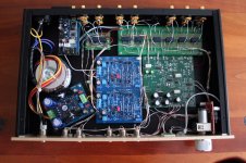
Really enjoying my preamp(s). Lots of interesting units here ..... you guys love your power supplies.
Thought I would share a few pics.
Left:
Remote volume and remote input switching.
Power supply is a knock-off of the "Super Regulator" which is out-of-stock here.
The other board is surface mount implementation of Carver Sonic Holography (default=bypassed).
4th input is Bluetooth.
External processor can be switched in (default=bypassed).
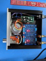
Right:
Remote volume
Power supply (hacked off another board) = +/-18V and +12V for the remote board power.
Thought I would share a few pics.
Left:
Remote volume and remote input switching.
Power supply is a knock-off of the "Super Regulator" which is out-of-stock here.
The other board is surface mount implementation of Carver Sonic Holography (default=bypassed).
4th input is Bluetooth.
External processor can be switched in (default=bypassed).
Right:
Remote volume
Power supply (hacked off another board) = +/-18V and +12V for the remote board power.
Attachments
not what I expected from such a well-regarded design
......... originally intended as line stage, not can amp
Left:
The other board is surface mount implementation of Carver Sonic Holography (default=bypassed).
4th input is Bluetooth.
Super nice, smoovj!
Would love to hear more about the surface mount Carver piece. I'm also a bit jealous of the Bluetooth input. What a great idea for when you find something on your phone and need to hear it now without all the hassles of cables and such. How do you put that device into search/connect mode?
Last edited:
Thanks for the comments.Would love to hear more about the surface mount Carver piece.
I think the Carver C-9 Sonic Holography Processor has an interesting affect that I sometimes enjoy. Thought I could shrink it using surface mount with relays for the switching. Make it small. I was looking for a project. I laid it out, got a handful of boards fabricated and built some up .... I think it has almost 200 surface mount components, mostly 0603 size. Built a few boards by hand. Note it has a 2 channel simple op-amp preamp in the upper right corner. I didn't load that part of it for this build as I was using the BA2018. Also has it's own regulation (+12V, -12V, +12V for remote board, also powers the BT module.
The BT was a bit of an afterthought. The module was cheap. I was worried a bit about digital noise. With BT selected, no input playing and the volume up around 12 o'clock, I can hear a bit of low level digital noise, but I'm OK with that. It can't be heard when BT source is playing and is non-existant with analog inputs selected. It's a nice feature for under $20. I did have to work hard to make everything fit ... much easier if it wasn't there. Easy to hook-up.I'm also a bit jealous of the Bluetooth input.
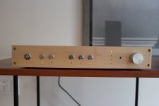
Front view attached.
Power
Disconnect (disconnects the outputs)
Ext Processor Select
Next 3 switches are for the Sonic Holography functions
Vertical LED column is input select - amber LEDS for 1-3, blue LED for BT.
Attachments
You are right. It was not my intention to offend anyone or diminish the project. I also consider this project a great line stage myself, I just wanted to get the same quality on headphones.......... originally intended as line stage, not can amp
For R18 it does not matter1/8w or 1/4w resistors?
Hi folks.…with relays for the switching.
Generally speaking, how do you select relays for audio signal duty?
I’ve used thousands of relays driving very heavy loads (single phase, capacitor-start motors - capactive inrush and inductive turn off - the perfect storm) but I’m certain that not much experience gained from that application can be transferred to delicate audio signals.
First you decide: latching relays or not-latching relays
Then you decide: which coil voltage(s) are acceptable
Then you decide: do I have any physical size constraints? Must the relay be the same size as a DIP-16 integrated circuit (a "reed relay")? Must it be no taller than H millimeters? etc.
Then you decide: what arrangement of contacts do I need? SPST-NO? SPDT? DPDT?
Then you decide: do I have any electrical constraints upon contact resistance?
Then you decide: which electronic distributors will I purchase from?
And finally you decide: do I insist upon purchasing relays with gold contacts so I can brag to my audio buddies?
- Home
- Amplifiers
- Pass Labs
- Wayne's BA 2018 linestage