Oh and use a big 3W for R39. Mine kept blowing up.
Well the BOM lists R37, R39 as 200 ohm 1/4 watt minimum, so if you need 3 watt resistors, then something isn't right with your amp.
Mine has been running for years with those 1/4 watt resistors, without a single failure.
jeff
")
Remove R64. Or for safety in case the pot goes open, change it to 1M.Hello everyone,
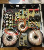
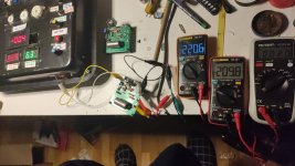
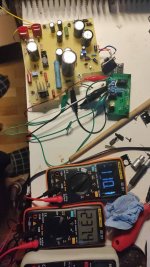
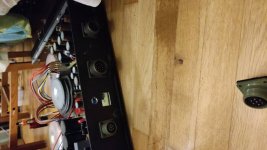
Ik have finished my build today! The amp sound really good. Ik have only one problem. I have added a volume pot. I have to turn the pot til the nine o'clock position to get enough amplification. Can you help me?
View attachment 1007207 View attachment 1007208 View attachment 1007209 View attachment 1007210
Pete
Ik have finished my build today!
Very nice! That volume pot looks interesting. Could I trouble you for a part number please?
jeff
It is a 24 steps potentiometer from eizz.Very nice! That volume pot looks interesting. Could I trouble you for a part number please?
jeff
https://www.amazon.com/s?k=eizz+pot...fix=eizz+potentiometer,aps,140&ref=nb_sb_noss
Egon

9:00 on the volume control sounds ok to me.
What is the voltage from your signal source? CD player, 2V rms maximum, or what?
How sensitive are your speakers; dB at 1 Watt at 1 meter?
If you consider your gain to be low, it is partly because:
1. The input pentodes have extremely high impedance plate rp (partly because you are using a current sink with the cathodes tied together; yes I realize you chose that kind of phase splitter).
I use a 12AY7 dual triode and constant current sink with the cathodes tied together, but I do not use schade negative feedback when using that kind of a splitter.
2. You are using Schade negative feedback. The input pentodes extremely high rp has to drive RL 30k in parallel with 220k feedback resistor.
3. You are also using Global Negative feedback which lowers the gain further.
Sorry i meant three o'clock position.....9:00 on the volume control sounds ok to me.
What is the voltage from your signal source? CD player, 2V rms maximum, or what?
How sensitive are your speakers; dB at 1 Watt at 1 meter?
If you consider your gain to be low, it is partly because:
1. The input pentodes have extremely high impedance plate rp (partly because you are using a current sink with the cathodes tied together; yes I realize you chose that kind of phase splitter).
I use a 12AY7 dual triode and constant current sink with the cathodes tied together, but I do not use schade negative feedback when using that kind of a splitter.
2. You are using Schade negative feedback. The input pentodes extremely high rp has to drive RL 30k in parallel with 220k feedback resistor.
3. You are also using Global Negative feedback which lowers the gain further.
So you do need more gain. OK.
I think I listed some of the items in Post # 1749 that cause low gain.
In my number 1 and number 2 items in that post, I was partly wrong.
The gain is more dependent on the 'operating Gm' of the input pentode x the 'plate load of 30k in parallel with 220k' (not the pentode's rp).
And since you are using a CCS constant current sink in the parallel cathodes of the input pentodes, the 'operating Gm' is effectively reduced to 1/2 of what it would be with AC grounded cathodes (which that kind of splitter can not do, it does not work with AC grounded cathodes).
In my number 3 item in that post, increasing the feedback resistor's resistance to 2x its original resistance can increase the gain of the amplifier (by up to 6 db, if the open loop gain is large enough versus the closed loop gain with global feedback). (increase 47k to 94k).
Last edited:
This amp design is a simplified derivative of the old RCA 50 watt design found in the back of several RCA tube manuals (page 696 in RC-30). I had been experimenting with a more simplified version that made about 10 watts from a pair of 6AU6's and a pair of 6AQ5's, so I grabbed one of Pete's new boards claiming that I wanted my money back if it wouldn't make at least 50 WPC. That turned out to be too easy of a goal. Over nearly two years I stuffed just about any tube that could be imagined into this board and tweaked the design to suit. I reached the limit at about 250 WPC, and 525 watts in paralleled mono with 35LR6 tubes for this board. At those levels nearly every component, including the board itself are on the verge of blowing up. I settled on a "safe" 125 WPC, published my mods somewhere in this thread, and made a few 125 WPC amps using 6HJ5 or 6HD5 tubes (not directly pin compatible do not try without making mods). There were about a dozen other 125 WPC amps built using the same recipe. All the info is scattered throughout this thread.
At power levels above 50 WPC low system gain is quite obvious. In order to be able to drive a 125 WPC version to clipping from a CD player more gain was in order. After trying every single 7 pin tube that will work in that socket including some that a "normal" user would never try. A 6BE6 pentagrid converter tube WILL work in this amp but provides no benefit. I settled on the oddball 6GU5 beam hexode. It's high Gm provides more gain and lower THD than the 6CB6. It is pin compatible and requires no other mods. In order to take advantage of the Gm I raised the plate load resistors to 39K. Pete used similar changes in his more conservative 50 watt mono block version. His thread on that amp may reveal more changes, but I haven't read either of these threads in several years.
At power levels above 50 WPC low system gain is quite obvious. In order to be able to drive a 125 WPC version to clipping from a CD player more gain was in order. After trying every single 7 pin tube that will work in that socket including some that a "normal" user would never try. A 6BE6 pentagrid converter tube WILL work in this amp but provides no benefit. I settled on the oddball 6GU5 beam hexode. It's high Gm provides more gain and lower THD than the 6CB6. It is pin compatible and requires no other mods. In order to take advantage of the Gm I raised the plate load resistors to 39K. Pete used similar changes in his more conservative 50 watt mono block version. His thread on that amp may reveal more changes, but I haven't read either of these threads in several years.
In theory a multi grid tube will make more overall noise than a triode, and that noise increased slightly with the number of grids. So, would I use the same hexode in the first stage of a high gain guitar amp? No, but for a totally different reason.Is it the case that heptodes and hexodes have a place in audio? I had thought that due the number of grids, partition noise would make them unsuitable?
The hexode is being used here as the driver for a TV sweep tube. The signal at its input is several hundred millivolts, so a few microvolts of noise would likely not be noticed unless very high efficiency speakers were used. It is not common to run a 125 WPC amp into high efficiency speakers, but I had one of my amps paired with EZ-10 horns filled with 99dB Audio Nirvana Super 10's. You had to put your ear next to the cone in a totally quiet room to hear any hiss. None was noticed a foot or so from the speakers. No, you didn't turn this combo up much, but it did sound nice and went very loud.
I built a high gain guitar amp with a 6AU6 in the first stage. The pentode was presented with a variable load impedance that could be adjusted from about 200K to about 2 megohm via a front panel pot. As with Pete's Big Red Board, I stuffed every tube I had into that first stage. Any tube in that amp becomes gain limited before the gain pot gets to full throttle, not by noise, but by microphonics. The 6GU5 was slightly noisier than the 6AU6, but far more microphonic. The 6BE6 was worst case. You could talk to the tube and hear your voice in the speaker with the gain pot at half throttle when the 6BE6 was installed. It did have a neat reverb quality, but the amp head had to be kept far away from the speaker to avoid feedback.
Hey guys, I am still reading through the read (on post #761 currently) but have a few priliminary questions.
1. Why 10R for the cathode resistors on the output tubes (R1, R19, R2, R15) instead of 1R? The 10R is magnifying the voltage/current 10x, maybe easier to read on lesser quality DMMs compared to no magnification?
2. Halfway through reading the thread and I like the idea of getting a bit more power out of the amp. In the original amp the PT is 280V-0-280V which is putting out ~390V DC. The B+ after regulation is 340V DC. Rather than getting a bigger PT to get more voltage couldnt the HV regulator circuit be finessed a bit to not drop so much voltage (hey MOSFETs and amp run cooer) and thus get a higher B+ (and power).
3. I see at one point pre-drilled top plates were avaible. Are those still around?
I think they were a one time deal. That was a long time ago, and haven't seen them since.3. I see at one point pre-drilled top plates were avaible. Are those still around?
jeff
Oops looks like I can't edit anymore
I did save this quote which I think may aid me (not sure who it is from).
I still think the easiest is to just to rig it with the 6HJ5, set the output to 400v B+, and select a 3.3k output transformer. That will give you 75 watts without having to worry about 500v caps and you wont have to bother with a external booster supply for the plates. I see no reason why you would need another 2.0db head room to move the full on 120watt version.
Back in post #138 I powered up the board for the first time. By using 350 volts of B+ and 6600 ohm OPT's I got 30 WPC. 50 watts came with an increase in supply voltage to 450 volts. Even more power can be found at higher voltages and lower impedance OPT's. Somewhere around 250 WPC was seen on 650 volts with a 2500 ohm OPT. That's probably way beyond the limits of the PC board itsels as some of the traces run too close to each other for that kind of voltage.
Hey George thanks for weighing in, I was hoping to get your insight on this.
I think I am going to go with the stock Edcor PT (hopefully it runs cooler with way less heater current draw due to the 6JH5s) which puts the B+ at ~340V.
Would it make sense to drop the impendance of the OTs even more than 6K6 to get a little more power at 340V? Maybe 4K?
I think I am going to go with the stock Edcor PT (hopefully it runs cooler with way less heater current draw due to the 6JH5s) which puts the B+ at ~340V.
Would it make sense to drop the impendance of the OTs even more than 6K6 to get a little more power at 340V? Maybe 4K?
- Home
- Amplifiers
- Tubes / Valves
- Posted new P-P power amp design