Strange, the lowest price 50V rated, 0.1uF, MLCC capacitors in SMD packages, all have the much better X7R dielectric:
link to DigiKey, sorted by price.
link to DigiKey, sorted by price.
Forget what I wrote about small physical size capacitors, 1206 X5R capacitors can also be quite non-linear.
To be precise, I used these:
Blocked
https://connect.kemet.com:7667/gate...ation/1.0/download/specsheet/C1206C106K3PACTU
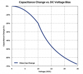
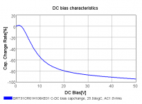
The non-linearity is as shown in the first attached picture; pretty bad, although not as bad as a similar Murata part (second attachment). The dielectric withstanding voltage is 2.5 times the rated working voltage, which probably explains why they haven't blown up yet.
The third graph is for a Murata capacitor meant for 50 V, as I should have used. It has actually only 12.8 % of its nominal value at 30 V.
To be precise, I used these:
Blocked
https://connect.kemet.com:7667/gate...ation/1.0/download/specsheet/C1206C106K3PACTU
The non-linearity is as shown in the first attached picture; pretty bad, although not as bad as a similar Murata part (second attachment). The dielectric withstanding voltage is 2.5 times the rated working voltage, which probably explains why they haven't blown up yet.
The third graph is for a Murata capacitor meant for 50 V, as I should have used. It has actually only 12.8 % of its nominal value at 30 V.
Attachments

I have some vague ideas for a new solid-state RTZ FIRDAC. If I ever work them out, I will probably start with something that could be used as a standalone DSD DAC. I don't know when and if that will happen, though.
Attached is a preliminary schematic. Now I only need to find time to design a PCB, stuff it and debug it
")
The circuit with the stacked dual transistors on page 2 is (or at least should be) a low-noise bandgap reference. I have the concept from an article in Electronics Letters from the late 1960's. It should have better noise performance than almost all modern bandgap references, because those almost always amplify a VBE difference by a large factor instead of stacking VBE differences. Only half the transistors are needed; I can't predict whether the BCM56DS or the NST45011 stacks will work best and they don't have the same footprints, so I want to reserve space for both.
The fifth page has a clock doubler and a return-to-zero circuit, among other things. JohnW doesn't like my earlier RTZ circuit because he is afraid that the switching of the flip-flop may disturb the gate output signal when the flip-flop isn't slow enough. To avoid that issue, in this circuit, I split the RTZ logic from the actual DAC.
74LV574A's connected as shift registers on the third and fourth pages are the logic circuits used as DACs, they have low-noise reference supplies that are separate from the RTZ logic supply. As they run on a doubled clock and there are zeros inserted between each pair of data bits, simple shift registers work as RTZ FIRDACs. It's like the DSC2 DACs, but with return to zero. It's a balanced four-tap FIRDAC, balanced to keep the load on the reference supply as data-independent as possible. For matching reasons, I've connected the 74LV574A flip-flops in an ABABABAB style, with a second 74LV574A in BABABABA style.
Attachments
Marcel,
I know you don't like to cut corners, but your voltage reference is rather voluminous.
The used dual transistors have no specified noise figure, that's why I simmed with the lowest available noise transistors, resp the ZTX851 and ZTX951.
I used the exact En, Enk, In and Ink figures for the used op-amp to match those from the OPA2210.
So what I have is as low as it gets, probably below the noise with the NXP duals.
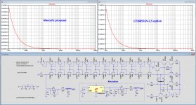
To compare I used the LTC6655LN-2.5, and what you can see in both graphs that they are absolutely comparable, with just one op-amp and to 10uF caps.
An idea for you to use ?
Hans
.
I know you don't like to cut corners, but your voltage reference is rather voluminous.
The used dual transistors have no specified noise figure, that's why I simmed with the lowest available noise transistors, resp the ZTX851 and ZTX951.
I used the exact En, Enk, In and Ink figures for the used op-amp to match those from the OPA2210.
So what I have is as low as it gets, probably below the noise with the NXP duals.
To compare I used the LTC6655LN-2.5, and what you can see in both graphs that they are absolutely comparable, with just one op-amp and to 10uF caps.
An idea for you to use ?
Hans
.
Attachments
I would really like to try the Electronics Letters reference, just for the hell of it, but I'll see if I can come up with a variant that uses the LTsomething instead.
There are ten shorts between the left and right transistor stacks in your schematic. Without those, the amplified reference voltage should be about 5 V. Any differences in noise should show up at deep subsonic frequencies where the filter capacitors haven't kicked in. The DAC will convert those to sidebands right next to the signal.
There are ten shorts between the left and right transistor stacks in your schematic. Without those, the amplified reference voltage should be about 5 V. Any differences in noise should show up at deep subsonic frequencies where the filter capacitors haven't kicked in. The DAC will convert those to sidebands right next to the signal.
I corrected the shorts and removed one set of transistors in the chain to hopefully match your circuit this time and have now:
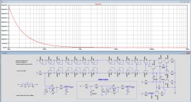
3.66 Volt for bgup and 4.51 Volt at the output of the OPA2210, see image below.
But forget the previous version with the LTC6655, because the one shown here is even simpler and uses the available 15Volt as input.
This ADR5041 may not be readily available but there are many replacements.
Hans
.
3.66 Volt for bgup and 4.51 Volt at the output of the OPA2210, see image below.
But forget the previous version with the LTC6655, because the one shown here is even simpler and uses the available 15Volt as input.
This ADR5041 may not be readily available but there are many replacements.
Hans
.
Attachments
Why do you prefer such a high noise reference?
TL431 -> 10 x lower noise, VG stability, 60c ea .....
I was just playing a bit with this ref theme, but what is against?
With the 100k and 100uF, output noise is under 1nV/rtHz from 10Hz and upwards, or are there other factors to consider.
Hans
Hans, you forgot the diode across R15 otherwise laaaawng ramp up time.
I've used this method for years watching people argue about expensive
so called low noise refs. The schottky pulls ref up to within 0.2V then the noise slooowly fades away.
TCD
Last edited:
Reference noise, subsonic or not, amplitude-modulates the signal and causes close-in sidebands around the spectral peaks of the signal. It's similar to the effect of the close-in phase noise of the clock that frequency-modulates the signal and causes sidebands, but in the case of phase noise you get an attenuation that depends on the clock-frequency-to-signal-frequency ratio, here you don't.
I doubt if either is very relevant considering masking, but there are people spending lots of time and money keeping sidebands due to close-in phase noise of the clocks small, so I thought I might as well use a reasonably low noise reference to keep the reference-related sidebands small as well - which gave me a nice pretext to finally build the Electronics Letters bandgap.
I doubt if either is very relevant considering masking, but there are people spending lots of time and money keeping sidebands due to close-in phase noise of the clocks small, so I thought I might as well use a reasonably low noise reference to keep the reference-related sidebands small as well - which gave me a nice pretext to finally build the Electronics Letters bandgap.
Reference noise, subsonic or not, amplitude-modulates the signal and causes close-in sidebands around the spectral peaks of the signal. It's similar to the effect of the close-in phase noise of the clock that frequency-modulates the signal and causes sidebands, but in the case of phase noise you get an attenuation that depends on the clock-frequency-to-signal-frequency ratio, here you don't.
I doubt if either is very relevant considering masking, but there are people spending lots of time and money keeping sidebands due to close-in phase noise of the clocks small, so I thought I might as well use a reasonably low noise reference to keep the reference-related sidebands small as well - which gave me a nice pretext to finally build the Electronics Letters bandgap.
With the diode bypass you can easily set the CF to 0.01Hz.... or is that too simple
TCD
- Home
- Source & Line
- Digital Line Level
- 74AHC02 and 74AHC08 DAC with 97 dB(A) dynamic range