Yes, q2. R69 3W holds here as wellAre you speaking of Q2 in the B+ ripple-filter ? On my 2 amps, I kept burning R69 (1Mohm). Replaced it with a large (3W I think) model and now it holds. Never burned the FET itself.
Last time during playing. Then at start up or shut down...The next I would check is the temperature/cooling. Does it blow at start or after playing for a while and after getting very hot ?
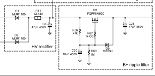
Mhh I'm not sure what happens here. So it happens at either brutal change (start/stop) and during normal operations. I guess you checked the output voltage after Q2 which should be around 340V and almost no ripple. What else could it be ? Consumption too high ? Is your amp using standard values for output tubes current/biasing ? Maybe a tube is EOL and is creating current spikes, killing Q2 ?
I once had a bad tube which produced cracking sound at random times and shifting biases. I had to move tubes around to identify it. It never blew Q2 though.
I once had a bad tube which produced cracking sound at random times and shifting biases. I had to move tubes around to identify it. It never blew Q2 though.
Mhh I'm not sure what happens here. So it happens at either brutal change (start/stop) and during normal operations. I guess you checked the output voltage after Q2 which should be around 340V and almost no ripple. What else could it be ? Consumption too high ? Is your amp using standard values for output tubes current/biasing ? Maybe a tube is EOL and is creating current spikes, killing Q2 ?
I once had a bad tube which produced cracking sound at random times and shifting biases. I had to move tubes around to identify it. It never blew Q2 though.
Well.
It is modified for working at 520 plate voltage. Capacitors are safe, with 550v max voltage.
No ripple.
Tubes are ok, perhaps also cold biased, at about 30mA or less at cathodes. The meters are spot on on the value, no drifts no spikes.
Still troubleshooting, no many ideas at this point.
65-70c is pretty hot for the heatsink. Perhaps the junction temperature is exceeding limits. If possible, try doubling the filter so you have 1 for each channel. Also more heatsink or airflow. I have used this sort of filter for over 20yrs in many tube amps, including a PPP 6550 amp with a current load of over .5amps at 420v. In that amp I use 2 filters to split the power dissipation. It has been running since 2001 with no issues. Oscillation can be a problem as well, but it looks like you have that covered with the 1k R gate stoppers.
I have seen 2 failure modes in this application. Oscillation was one and the other was mounting insulator failure. In other high voltage circuitry I have seen electrolytic capacitors fail and draw DC current without actually shorting. This eventually leads to the cap overheating and shorting, or the power supply fails, hopefully by blowing a fuse, but if not it will fail at the weakest point.
If you have a peak reading DVM it may be useful to monitor the output voltage to see if you are dealing with an over voltage condition.
Do you have any chokes in the power supply filters? Undamped voltage can spike and exceed the rating of the output FET.
So, after half a year it works a charm, but continues burning the mosfet in the b+ line. Already equipped a 900V one, from time to time it gets shot, and can't understand why?
The mosfet that you are using was not designed for use in the linear region. The data sheet shows a copyright date of 2016. At that time many semiconductor manufacturers continued to believe that secondary breakdown, a common failure mechanism in bipolar transistors, did not exist in mosfets. We now know that it is real and causes exactly what you are seeing. On Semi / Fairchild still does not recognize this in their data sheets. They have quietly removed all mosfets from the audio amplifier section of their product selection guide.
Any data sheet where the SOA graph for DC is exactly equal to the rated dissipation is NOT to be trusted. Likewise any mosfet that does not have a curve on the SOA graph for DC, or shows no SOA curve at all can not be used in a linear circuit like a voltage regulator.
Mosfets like this one where all of the suggested applications are digital (SMPS and other switching applications) can not be used with a constant DC dissipation across them. I have found that the term "push pull amplifier" can refer to a class D circuit, and these part may blow in a linear application.
There are some mosfets made for use in "class AB" audio amps, linear power supplies, and other linear applications. These will not blow up. The secondary breakdown mode is far less in a Depletion mode mosfet, so these MAY be used in some cases. Check the SOA curve to see if your operating conditions are well within the specs. I have been using IXYS L2 (linear) and some of their depletion mode fets with good results, but they are somewhat hard to find in today's market.
Look for parts like IXTP15N50L2, a nearly impossible to blow linear fet. Note that this part crested for linear operation and rated for "300 watts" is only guaranteed for 150 watts in the middle of its linear region (400 volts at 375 mA)
Or IXTP3N50D2 and IXTP3N100D2 these are depletion fets that I have used in big amps, but will cause a slight reduction in screen voltage.
I have been working on new concept tube amp design that pairs a TV sweep tube and a mosfet to create a "device" that has near perfect triode curves. The work has been going on for several years, resulting in lots of blown mosfets. Coincidentally my work at Motorola right before I retired involved investigations of the secondary breakdown effect in GaN fets used in RF transmitters. Some of my findings are scattered throughout these threads:
UNSET is coming?
Single Ended: the pentode retaliation
If UNSET and the RCA50W Had a Baby
Shunt Cascode Driver meets UNSET for Push-Pull
Last edited:
Thanks thanks!The mosfet that you are using was not designed for use in the linear region. The data sheet shows a copyright date of 2016. At that time many semiconductor manufacturers continued to believe that secondary breakdown, a common failure mechanism in bipolar transistors, did not exist in mosfets. We now know that it is real and causes exactly what you are seeing. On Semi / Fairchild still does not recognize this in their data sheets. They have quietly removed all mosfets from the audio amplifier section of their product selection guide.
Any data sheet where the SOA graph for DC is exactly equal to the rated dissipation is NOT to be trusted. Likewise any mosfet that does not have a curve on the SOA graph for DC, or shows no SOA curve at all can not be used in a linear circuit like a voltage regulator.
Mosfets like this one where all of the suggested applications are digital (SMPS and other switching applications) can not be used with a constant DC dissipation across them. I have found that the term "push pull amplifier" can refer to a class D circuit, and these part may blow in a linear application.
There are some mosfets made for use in "class AB" audio amps, linear power supplies, and other linear applications. These will not blow up. The secondary breakdown mode is far less in a Depletion mode mosfet, so these MAY be used in some cases. Check the SOA curve to see if your operating conditions are well within the specs. I have been using IXYS L2 (linear) and some of their depletion mode fets with good results, but they are somewhat hard to find in today's market.
Look for parts like IXTP15N50L2, a nearly impossible to blow linear fet. Note that this part crested for linear operation and rated for "300 watts" is only guaranteed for 150 watts in the middle of its linear region (400 volts at 375 mA)
Or IXTP3N50D2 and IXTP3N100D2 these are depletion fets that I have used in big amps, but will cause a slight reduction in screen voltage.
I can instead continue using the fairchild on the screen side, and the ixys you're saying on the b+, right? Are a straight replacement, right?
And George you're right. With about 560 b+ voltage and some 120 mA we're at the limit for the FQPF8N90C, the 60C is well out of spec. Had a look at your indicated ixys mosfet, yet they're rated for max 500V (unless I find some more powerful ones), and also herey working range is out of spec
I can instead continue using the fairchild on the screen side, and the ixys you're saying on the b+, right? Are a straight replacement, right?
One of the L2 mosfets should work directly with a minor change in B+ voltage due to different threshold voltages. Any depletion mode fet will cause a larger change in output voltage, and may not work in all circuits.
And George you're right. With about 560 b+ voltage and some 120 mA we're at the limit for the FQPF8N90C, the 60C is well out of spec. Had a look at your indicated ixys mosfet, yet they're rated for max 500V (unless I find some more powerful ones), and also herey working range is out of spec
I have thoroughly tested the IXYS mosfets in my latest amplifier design. It is nothing like Pete's big red board which you are operating beyond it's original design parameters. I still have a big red board, but it has not seen power in several years. It, occupied my workbench in Florida for almost two years, and spawned a 125 WPC version, and two complete amplifiers.
My bench is currently filled with other distractions including a new tube amp design. I ran my big red board at 600 to 650 volts, but after blowing up a lot of parts, I came up with the two power transformer approach. I use one transformer to feed the board enough power for a B+ in the 325 volt range. It works well with all stock parts. The second transformer creates a second power supply of about 300 volts which is stacked on top of the first, and feeds only the red wires on the OPT's (output tube plates). The details are somewhere in the thread.
I would not use a 500 volt part on more than 500 volts. I simply listed the parts that I have personally tested in my amp design which only feeds the output tube screens. There are other L2 fets, and other fets with specified, and even guaranteed SOA ratings from IXYS and others. In my case I am using the 500 volt fet, and my B+ is 650 volts, but the current through the fet is limited with large resistor in series with the drain, and the output is set to 190 volts putting 460 volts across the fet.
Someone needs to sticky that comment for the tubelab approved mosfets.
Unfortunately in todays semiconductor world new mosfets come and go, with extremely variable product lifetimes. I have seen new fets announced, and go end of life in the same year. If a fet or other semiconductor device doesn't find a "million units a month" product to live in, it dies, often with only one production run.
What about a STP6N120K3 ?
This part does NOT show a DC curve on the SOA plots. See page 6-17 in the data sheets. This means that it was not intended for linear operation, failures have been seen in linear mode, or ST has not tested them sufficiently enough to specify linear operation. As you have found these failures are random and often take a year or so to materialize.
As I stated before, I have seen several ON semi / Fairchild part fail when operated well within their published SOA ratings. I am also using a Fairchild P channel part in my current amp with no issues at 60C, but am actively investigating all possible alternatives since these failures are still not well understood.
Any suggestions for P channel audio mosfets?
So please George, would you be so kind to name a plug-in mosfet for this amp? Running at 540V B+, i took a look at mosfet with DC SOA but couldn't find anything.One of the L2 mosfets should work directly with a minor change in B+ voltage due to different threshold voltages. Any depletion mode fet will cause a larger change in output voltage, and may not work in all circuits.
I have thoroughly tested the IXYS mosfets in my latest amplifier design. It is nothing like Pete's big red board which you are operating beyond it's original design parameters. I still have a big red board, but it has not seen power in several years. It, occupied my workbench in Florida for almost two years, and spawned a 125 WPC version, and two complete amplifiers.
My bench is currently filled with other distractions including a new tube amp design. I ran my big red board at 600 to 650 volts, but after blowing up a lot of parts, I came up with the two power transformer approach. I use one transformer to feed the board enough power for a B+ in the 325 volt range. It works well with all stock parts. The second transformer creates a second power supply of about 300 volts which is stacked on top of the first, and feeds only the red wires on the OPT's (output tube plates). The details are somewhere in the thread.
I would not use a 500 volt part on more than 500 volts. I simply listed the parts that I have personally tested in my amp design which only feeds the output tube screens. There are other L2 fets, and other fets with specified, and even guaranteed SOA ratings from IXYS and others. In my case I am using the 500 volt fet, and my B+ is 650 volts, but the current through the fet is limited with large resistor in series with the drain, and the output is set to 190 volts putting 460 volts across the fet.
Unfortunately in todays semiconductor world new mosfets come and go, with extremely variable product lifetimes. I have seen new fets announced, and go end of life in the same year. If a fet or other semiconductor device doesn't find a "million units a month" product to live in, it dies, often with only one production run.
This part does NOT show a DC curve on the SOA plots. See page 6-17 in the data sheets. This means that it was not intended for linear operation, failures have been seen in linear mode, or ST has not tested them sufficiently enough to specify linear operation. As you have found these failures are random and often take a year or so to materialize.
As I stated before, I have seen several ON semi / Fairchild part fail when operated well within their published SOA ratings. I am also using a Fairchild P channel part in my current amp with no issues at 60C, but am actively investigating all possible alternatives since these failures are still not well understood.
Any suggestions for P channel audio mosfets?
Thank you.

Any comments on using this https://www.tme.com/ca/en/details/ttg-kt88pp/toroidal-transformers/toroidy/ as output transformer? How it compares to Edcor (except a little less power)
I have built an engineer amp using Toroody. Works extremely well, see its look here : Integrated Amplifier – Deep Lake AudioAny comments on using this TTG-KT88PP TOROIDY - Transformer: speaker | 80VA; O115x65mm; 0.012/56kHz; 300mA | TME - Electronic components as output transformer? How it compares to Edcor (except a little less power)

Oh and use a big 3W for R39. Mine kept blowing up.I have built an engineer amp using Toroody. Works extremely well, see its look here : Integrated Amplifier – Deep Lake Audio
- Home
- Amplifiers
- Tubes / Valves
- Posted new P-P power amp design