Hello Ian,
Using these 3 stand off surely makes it look more solid
Probably there will be people who would like to give this tiny board its separate 3,3 volt.
Maybe there is something that can be done to make it more easily??
Greetings, eduard
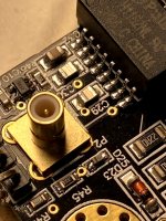
Well, directly underneath is the Fifopi q3, which has a 3,3 volt input.
Otherwise you would have one for the relock logic and also one for the squarer? Not sure if that is necessary ? Ian ?
FWIW, I did experiment with separate power to a NDK SDA pcb using low noise reg, blackgate caps and a supercap. It was at least one of those little dots that add up. Power to the clock is shared with the IC that outputs mclk so perhaps some small advantage to individual power supplies. I also popped a blackgate HiQ cap onto Andrea's squarer and to my ear it cleaned up the sound. I don't have a scope so no idea if it cleaned up the squiggly square wave. Not worth talking about as these thing are unavailable but simply mention as it suggests improvement is there to be had which we'll likely see with SinePi.Otherwise you would have one for the relock logic and also one for the squarer? Not sure if that is necessary ? Ian ?
HDMIpi transmitter picoreplayer, (Squeezelite), settings
Hi, maybe a bit misplaced but I it a try anyway")
I have a HDMIpi transmitter connected to a rpi4 using picoreplayer, which is feeding a Denafrips Pontus II DAC.
The issue with my current setup is sample rate limitations and lack of DSD capability => no function for sampling rates above 192kHz and no native DSD output.
Current settings:
- Audio output device settings: RPi DAC
- Output setting: hw:CARD=sndrpirpidac
From my understanding the sndrpirpidac uses the pcm1794a codec which I believe is the bottleneck and limiting the sampling rate.
Is there anyone else that has the same issue or can advise in different settings unlocking the true capability of HDMIpi using picoreplayer?
Hi, maybe a bit misplaced but I it a try anyway
I have a HDMIpi transmitter connected to a rpi4 using picoreplayer, which is feeding a Denafrips Pontus II DAC.
The issue with my current setup is sample rate limitations and lack of DSD capability => no function for sampling rates above 192kHz and no native DSD output.
Current settings:
- Audio output device settings: RPi DAC
- Output setting: hw:CARD=sndrpirpidac
From my understanding the sndrpirpidac uses the pcm1794a codec which I believe is the bottleneck and limiting the sampling rate.
Is there anyone else that has the same issue or can advise in different settings unlocking the true capability of HDMIpi using picoreplayer?
Hello,
Andrea told us that giving his STS solution a seperate 3,3 volt supply would be a good idea. Just like Ian told us that giving the reclockpi a separate 3,3 volt is also good.
Because of this i have a 4 separate 3,3 volt supplies, so 4 3,3 volt lifepo4 cells and three of them have an UcHybrid board in parallel.
Ian told us somewhere that his new tiny board is complicated because of Rf/Hf related things. So maybe it is good to give it its own supply so possible '' disturbances '' cannot '' skip '' from one circuit to another by means of a joined power supply.
Once you have the lifepo4 board creating an extra 3,3 volt supply is pretty easy and the cost isnt to high.
OF COURSE in the near future people will face the dilemma of going for one pair of 3000F caps, keeping 3 or 4 lifepo4 cells with smaller ultracaps or going for a big volume of 3000F caps.
I THINK that people should focus more on keeping connections between big F caps and the circuits as direct and as short as possible. Of course the currents we are using are very small so we dont need big terminals that can withstand the currents that these F caps can deliver. BUT if you will use a flimsy connector you might as well use a smaller cap.
Greetings, eduard
Trying to get the most out of TWTMC clocks for FifoPi system (8)
SinePi V6 squarer time domain testing results
To design a Sine to square wave converter (squarer) is not difficult. But to optimize the performance to a higher level really needs many jobs and has to take a lot of design considerations. That’s why I had made/revised the SinePi PCB for 6 times until I’m happy with the results. Even now, I am still struggling if I can finalize the design.
A DAC is run by edges of the square clocks to perform the timing of the digital to analog conversion, not the phase of the sine clocks . Without a good squarer, low phase noise sine clocks will be wasted. That’s why a squarer is very important for sound quality. Actually, in most of the cases, when you try to feed a sine clock into a DAC you will still get the sound as long as the amplitude is within the logic level range (can use a diode to clamp the negative voltage) . However the DAC performance will be degraded because of the much higher jitter level and other timing uncertainties due to the very slow slew rate of the sine clocks (Just think of how the clocks were received in a DAC or receiver side).
A sine to square wave converter can be considered as a high gain amplifier and the bridge between the phase domain and the time domain. So to figure out the output square wave quality, time domain measurements would be necessary.
Following are the time domain testing results of my SinePi V6 by comparing with TWTMC-STS under the same conditions and at the same time:
1.Waveform measurements
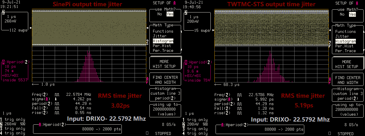
The left of the first picture shows the waveform of the SinePi output with sine wave input from a TWTMC-DRIXO-22.5792 MHz.
We can see the rising and falling edges are very fast around 0.54ns. No overshoot. There are only very small ringings within 10ns after both rising and falling edges, which were caused by the transmission line (there is no perfect impedance matched cable and connectors in the real world). Both high and low logic levels are very clean. While STS’s rising and falling time are around 1.3ns, and with overshoot, bigger ringings and more noise at both high and low levels. By comparing with the TWTMC-STS output waveform (right side) under the same testing conditions, we can figure out obviously how much improvements have been made by the SinePi.
To recall my previous waveform test:
https://www.diyaudio.com/forums/dig...mate-weapon-fight-jitter-664.html#post6678025
2.Time jitter measurements
The left side of the second picture shows the time jitter plot of the SinePi output with a TWTMC-DRIXO-22.5792 MHz sine clock as input.
The SinePi RMS time jitter was measured at 3.02ps (with LC584AXL timebase noise floor removed). I never expected this number to be better than a CCHD957 because Andrea already confirmed by his phase noise measurement that the CCHD957 has a lower noise floor than DIRXO. However, with SinePi installed, this RMS time jitter number is now very close to the CCHD957 which was measured at 2.71ps. By comparing with the TWTMC-STS time jitter plot (at the right side), we can see that the SinePi improves the RMS time jitter by 2.17ps (5.19ps-3.03ps) for DRIXO. That’s a huge improvement over TWTMC-STS. I believe, with a SinePi installed, it now really represents the true performance of the great TWTMC-DIRXO in the form of square wave for what it should be.
To recall my previous time jitter test:
https://www.diyaudio.com/forums/dig...mate-weapon-fight-jitter-662.html#post6675622
3.Testing conditions:
LC584AXL 1GHz Oscilloscope with jitter measurement package
Time base 10ns/div
Run at 8 GS/s sampling with 1GHz bandwidth fully opened
50 ohm terminated coaxial cable input. Cable length 4 inches.
TWTMC-DIRXO power supply: 13.2V LifePO4
SinePi and TWTMC-STS power supply: pure 3000F ultracapacitor precharged to 3.3V (could be the best PSU in the real world)
TWTMS-DIRXO 22.5792 MHz sine clock as input
Some notes about my measurements.
1.My LC584AXL was officially calibrated 7 years ago. After so many years, I can not guarantee it’s 100% accurate. But the apple to apple comparison testing results will make more sense to figure out the improvements.
2. LC584AXL has 2ps noise floor on jitter measurements according to the specification. But the actual noise floor number could be between 2ps and 3ps because of the aging of the timebase.So I’ll pick 3ps to represent the worst cases.
3. I’m not a qualified testing lab, so the testing on Andrea’s products could be unfair for him. The reason I tested his TWTMC-STS as a comparison reference was because I bought TWTMC clocks and TWTMC-STS boards from him trying to improve my system. But I was not happy with TWTMC-STS’s performance and there was no other solution at the time, so I had no choice but to design the SinePi by myself looking for improvements for both measurements and the sound quality.
4.There is no problem if anybody is questioning my testing results. Feel free to duplicate my test by yourself and let me know if your results are different. For this time domain measurement, please do use a high speed digital oscilloscope with bandwidth higher than 1GHz and simple rate higher than 8GS/s. Otherwise you will miss many details.
5. What I’m doing is exactly as same as the title: trying to get the most out of TWTMC clocks
Other links:
1.https://www.diyaudio.com/forums/dig...mate-weapon-fight-jitter-657.html#post6668751
2.https://www.diyaudio.com/forums/dig...mate-weapon-fight-jitter-660.html#post6671042
3.https://www.diyaudio.com/forums/dig...mate-weapon-fight-jitter-662.html#post6675622
4.https://www.diyaudio.com/forums/dig...mate-weapon-fight-jitter-664.html#post6678025
5.https://www.diyaudio.com/forums/dig...mate-weapon-fight-jitter-673.html#post6686256
6.https://www.diyaudio.com/forums/dig...mate-weapon-fight-jitter-677.html#post6690153
7.https://www.diyaudio.com/forums/dig...mate-weapon-fight-jitter-682.html#post6704886

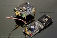
SinPiV6OutputWaveform by Ian, on Flickr
SinPiV6OutputTimeJitter by Ian, on Flickr

SinePiV6.0 by Ian, on Flickr
Ian
SinePi V6 squarer time domain testing results
To design a Sine to square wave converter (squarer) is not difficult. But to optimize the performance to a higher level really needs many jobs and has to take a lot of design considerations. That’s why I had made/revised the SinePi PCB for 6 times until I’m happy with the results. Even now, I am still struggling if I can finalize the design.
A DAC is run by edges of the square clocks to perform the timing of the digital to analog conversion, not the phase of the sine clocks . Without a good squarer, low phase noise sine clocks will be wasted. That’s why a squarer is very important for sound quality. Actually, in most of the cases, when you try to feed a sine clock into a DAC you will still get the sound as long as the amplitude is within the logic level range (can use a diode to clamp the negative voltage) . However the DAC performance will be degraded because of the much higher jitter level and other timing uncertainties due to the very slow slew rate of the sine clocks (Just think of how the clocks were received in a DAC or receiver side).
A sine to square wave converter can be considered as a high gain amplifier and the bridge between the phase domain and the time domain. So to figure out the output square wave quality, time domain measurements would be necessary.
Following are the time domain testing results of my SinePi V6 by comparing with TWTMC-STS under the same conditions and at the same time:
1.Waveform measurements
The left of the first picture shows the waveform of the SinePi output with sine wave input from a TWTMC-DRIXO-22.5792 MHz.
We can see the rising and falling edges are very fast around 0.54ns. No overshoot. There are only very small ringings within 10ns after both rising and falling edges, which were caused by the transmission line (there is no perfect impedance matched cable and connectors in the real world). Both high and low logic levels are very clean. While STS’s rising and falling time are around 1.3ns, and with overshoot, bigger ringings and more noise at both high and low levels. By comparing with the TWTMC-STS output waveform (right side) under the same testing conditions, we can figure out obviously how much improvements have been made by the SinePi.
To recall my previous waveform test:
https://www.diyaudio.com/forums/dig...mate-weapon-fight-jitter-664.html#post6678025
2.Time jitter measurements
The left side of the second picture shows the time jitter plot of the SinePi output with a TWTMC-DRIXO-22.5792 MHz sine clock as input.
The SinePi RMS time jitter was measured at 3.02ps (with LC584AXL timebase noise floor removed). I never expected this number to be better than a CCHD957 because Andrea already confirmed by his phase noise measurement that the CCHD957 has a lower noise floor than DIRXO. However, with SinePi installed, this RMS time jitter number is now very close to the CCHD957 which was measured at 2.71ps. By comparing with the TWTMC-STS time jitter plot (at the right side), we can see that the SinePi improves the RMS time jitter by 2.17ps (5.19ps-3.03ps) for DRIXO. That’s a huge improvement over TWTMC-STS. I believe, with a SinePi installed, it now really represents the true performance of the great TWTMC-DIRXO in the form of square wave for what it should be.
To recall my previous time jitter test:
https://www.diyaudio.com/forums/dig...mate-weapon-fight-jitter-662.html#post6675622
3.Testing conditions:
LC584AXL 1GHz Oscilloscope with jitter measurement package
Time base 10ns/div
Run at 8 GS/s sampling with 1GHz bandwidth fully opened
50 ohm terminated coaxial cable input. Cable length 4 inches.
TWTMC-DIRXO power supply: 13.2V LifePO4
SinePi and TWTMC-STS power supply: pure 3000F ultracapacitor precharged to 3.3V (could be the best PSU in the real world)
TWTMS-DIRXO 22.5792 MHz sine clock as input
Some notes about my measurements.
1.My LC584AXL was officially calibrated 7 years ago. After so many years, I can not guarantee it’s 100% accurate. But the apple to apple comparison testing results will make more sense to figure out the improvements.
2. LC584AXL has 2ps noise floor on jitter measurements according to the specification. But the actual noise floor number could be between 2ps and 3ps because of the aging of the timebase.So I’ll pick 3ps to represent the worst cases.
3. I’m not a qualified testing lab, so the testing on Andrea’s products could be unfair for him. The reason I tested his TWTMC-STS as a comparison reference was because I bought TWTMC clocks and TWTMC-STS boards from him trying to improve my system. But I was not happy with TWTMC-STS’s performance and there was no other solution at the time, so I had no choice but to design the SinePi by myself looking for improvements for both measurements and the sound quality.
4.There is no problem if anybody is questioning my testing results. Feel free to duplicate my test by yourself and let me know if your results are different. For this time domain measurement, please do use a high speed digital oscilloscope with bandwidth higher than 1GHz and simple rate higher than 8GS/s. Otherwise you will miss many details.
5. What I’m doing is exactly as same as the title: trying to get the most out of TWTMC clocks
Other links:
1.https://www.diyaudio.com/forums/dig...mate-weapon-fight-jitter-657.html#post6668751
2.https://www.diyaudio.com/forums/dig...mate-weapon-fight-jitter-660.html#post6671042
3.https://www.diyaudio.com/forums/dig...mate-weapon-fight-jitter-662.html#post6675622
4.https://www.diyaudio.com/forums/dig...mate-weapon-fight-jitter-664.html#post6678025
5.https://www.diyaudio.com/forums/dig...mate-weapon-fight-jitter-673.html#post6686256
6.https://www.diyaudio.com/forums/dig...mate-weapon-fight-jitter-677.html#post6690153
7.https://www.diyaudio.com/forums/dig...mate-weapon-fight-jitter-682.html#post6704886
SinPiV6OutputWaveform by Ian, on Flickr
SinPiV6OutputTimeJitter by Ian, on Flickr
SinePiV6.0 by Ian, on Flickr
Ian
Attachments
D
Deleted member 537459
It nails a bunch of the design objectives.
- sturdy mount for SMA cables
- switching of clocks that do not support the select pin
- mix of sine and square wave input
- cleaned up the square wave
Nice work!
Two important measures left:
- Does it also affect perceived sound of a system driven by DRIXO / STS?, and
- Price?
- sturdy mount for SMA cables
- switching of clocks that do not support the select pin
- mix of sine and square wave input
- cleaned up the square wave
Nice work!
Two important measures left:
- Does it also affect perceived sound of a system driven by DRIXO / STS?, and
- Price?
Hi,
maybe I am to late for the party:
I tried to read as much as possible. But the questions keep coming
At the moment I use a Buffalo III-SE Pro (ESS 9038) DAC with Mercury I/V stage form twisted pear.
I feed it with Roon to their BeagleBoneBlack(with botic driver) -->Hermes--> Chorus combo with quite some problems. (When it is working it sounds great)
I am quite happy with the DAC and would like to optimize the "streamer"-side. So I would like to go the Roon --> RPi4-->FifoPi--> ReclockPi --> ??? way.
My main questions are: what is the best way to connect the FifoPi to the Buffalo for I2S.
Is there an option for an extra Streamer case or has it be in the same case as the DAC?
Thank you
Branko
It nails a bunch of the design objectives.
- sturdy mount for SMA cables
- switching of clocks that do not support the select pin
- mix of sine and square wave input
- cleaned up the square wave
Nice work!
Two important measures left:
- Does it also affect perceived sound of a system driven by DRIXO / STS?, and
- Price?
Thanks Wlowes,
I'm still working very hard trying to improve the sound quality even more to my DAC with the TWTMC clocks.
Indeed, the sine to square wave converter (squarer) is a simple circuit. But it’s very sensitive to many different things. A lot of issues have to be addressed by SinePi, such as topology, power supply noise, common mode ground noise, trace impedance matching,channel isolation, limitation, vibration, interference, slew rate and so on.
https://www.diyaudio.com/forums/dig...mate-weapon-fight-jitter-687.html#post6718041
More update will be posted.
Ian
Hi,
maybe I am to late for the party:
I tried to read as much as possible. But the questions keep coming
At the moment I use a Buffalo III-SE Pro (ESS 9038) DAC with Mercury I/V stage form twisted pear.
I feed it with Roon to their BeagleBoneBlack(with botic driver) -->Hermes--> Chorus combo with quite some problems. (When it is working it sounds great)
I am quite happy with the DAC and would like to optimize the "streamer"-side. So I would like to go the Roon --> RPi4-->FifoPi--> ReclockPi --> ??? way.
My main questions are: what is the best way to connect the FifoPi to the Buffalo for I2S.
Is there an option for an extra Streamer case or has it be in the same case as the DAC?
Thank you
Branko
My guess is it would be in the same case as the dac because you need to connect it through i2s and these cables need to be as short as possible.
If I remember correctly the buffalo board has ufl connectors for i2s.
Hello,
If vibration is an issue i will use some kind of vibration killing mounting kind to isolate the complete fifopi unit and everything mounted on top of it if possible. Maybe just use something to isolate the aluminium sheet that is used for mounting most circuit boards.
A little extra weight will make it easier to kill vibrations.
We will see.
Greetings,Eduard
Holco. Do you find better subjective SQ elsewhere or just wanting a new project?
I bought a Auralic Aries G1 streamer, the reason is I want some tidiness in my setup and am very happy with the Lightning DS software from Auralic, they don't differ much in terms of sound.
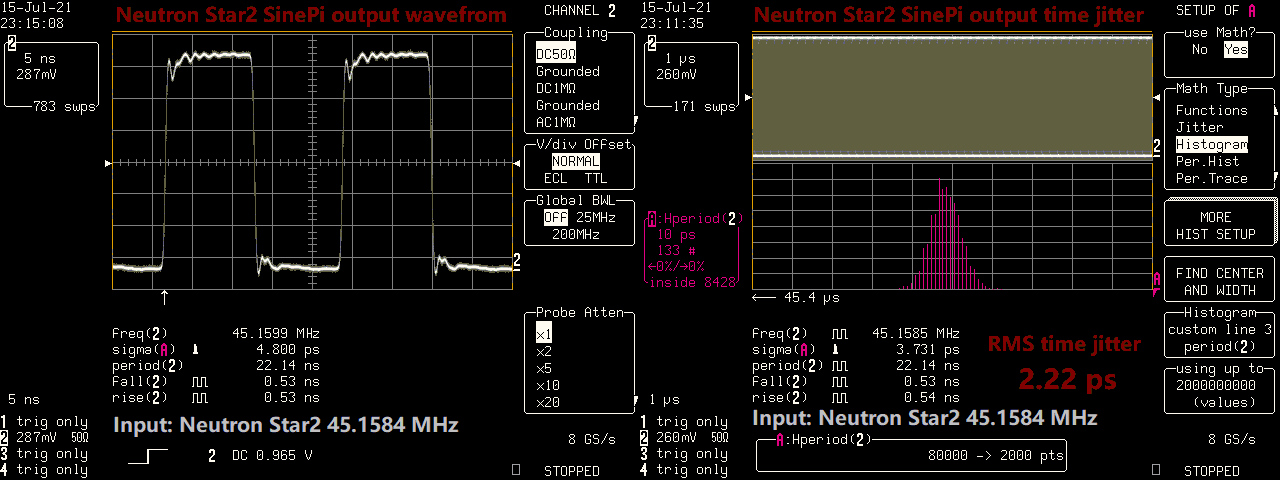
OCXO 45.1584 MHz Neutron Star2 SMB sine output with SinePi, time domain measurement results:
1.Rising/falling time: 0.53 ns
2.RMS time jitter: 2.22ps
3.Real frequency: 45.1585 MHz
Seems Neutron Star2 has lower RMS time jitter
To make Neutron SMB coaxial cable output work better with SinePi, I removed the clamp diode D25. This diode was used to cut the negative voltage of the output. But can change the duty cycle less than 50%.
BTW, Neutron Star2 has an on-board oven.
To recall DRIXO with SinePi testing result
https://www.diyaudio.com/forums/dig...mate-weapon-fight-jitter-687.html#post6718041
NeutronStar2SinePi by Ian, on Flickr
Ian
Attachments
soundcheck's - audio@vise: DSD streaming - a guidelineThe issue with my current setup is sample rate limitations and lack of DSD capability => no function for sampling rates above 192kHz and no native DSD output.
just gone Daphile, and it is the bees knees - Software - Audiophile StyleStart with ":u32be" if the DAC manufacturer hasn't communicated anything specific about it. If that doesn't work run the "trial and error" method and try each of them.
just gone Daphile, and it is the bees knees - Page 2 - Software - Audiophile Style(my DAC is a Denafrips Ares II)
Finally worked out that I needed to change the pCP "Device supports DSD/DoP" setting to 3:u32be (at least for my setup) and now DSD sounds fine.
Hi guys , after some help getting my dac to mute at the begining and end of tracks as there are loud pops now that I am trialling an hdmi connection instead of spidf.
I am using a FIFO PI q3 with a transport pi, hdmi connecto,r going to a Reciver pi which feeds an I2S header on the dac. I have all the 'data' lines and ground connected between the output of the reciver pi and the input header on the dac but the dac does not mute when starting a new album or when the album ends.
The Q3 has a header for a mute signal and I am wondering if I should just connect that to the mute pin in the dac header via a completely seperate cable between streamer and dac or if there is a more elegant solution.
Thanks in advance ,
Gordon
- Home
- Source & Line
- Digital Line Level
- Asynchronous I2S FIFO project, an ultimate weapon to fight the jitter