Ok, thank you for the confirmation that I'm not totally wrong in my simulation experiment ") Maybe the same cap placement has even been posted earlier in the thread too. I just wanted to try it since I saw something that looked similar in one of member bonsai's amps here on the forum.
Maybe the same cap placement has even been posted earlier in the thread too. I just wanted to try it since I saw something that looked similar in one of member bonsai's amps here on the forum.
I'm not sure if I will actually modify the amp, since I did not see any oscillation problem before while testing it.
The input filter was needed with the amp sitting next to my old plasma TV, not sure if it's needed now that I replaced the TV.
I tried the floating ground a long time ago and thought it improved the bass a bit, and overall sound to if I remember correctly. I think it can be beneficial running switched PSU's as I do, it evens out the current draw from the PSU if I rember my simulations correctly. EDIT: I should refer to the 'sublimed JLH' which gave me the idea.
I saw the LF oscillations with stepped input signals and correctly spaced bursts on the bench, but have never seen the woofers 'swing' at LF while playing music. With my oversized bootstrap cap, the current rises slowly at turn on, so there is no big movement even then.
Maybe the same cap placement has even been posted earlier in the thread too. I just wanted to try it since I saw something that looked similar in one of member bonsai's amps here on the forum. I'm not sure if I will actually modify the amp, since I did not see any oscillation problem before while testing it.
The input filter was needed with the amp sitting next to my old plasma TV, not sure if it's needed now that I replaced the TV.
I tried the floating ground a long time ago and thought it improved the bass a bit, and overall sound to if I remember correctly. I think it can be beneficial running switched PSU's as I do, it evens out the current draw from the PSU if I rember my simulations correctly. EDIT: I should refer to the 'sublimed JLH' which gave me the idea.
I saw the LF oscillations with stepped input signals and correctly spaced bursts on the bench, but have never seen the woofers 'swing' at LF while playing music. With my oversized bootstrap cap, the current rises slowly at turn on, so there is no big movement even then.
Last edited:
On re-reading your results, I don't get phase angles of 224 degrees. Where are you inserting the Tian probe? The phase shift I get at midband (~1kHz) is around 0 degrees, going negative at higher. Sometimes the simulations can interpret zero as 360.
Correction- your sim continues past 100MHz. Maybe OK after all!
Correction- your sim continues past 100MHz. Maybe OK after all!
I also want to recommend Sandro's youtube video's and thread here on the forum, which helped understand a little bit more about amps and simulation (I still know almost nothing), and in this case simulating stability.
SW-VFA-01: Audio power amplifier video series
3.2. Measuring Loop gain and Open loop gain in LTSpice - Audio Amplifier Design Fundamentals - YouTube
SW-VFA-01: Audio power amplifier video series
3.2. Measuring Loop gain and Open loop gain in LTSpice - Audio Amplifier Design Fundamentals - YouTube
Where are you inserting the Tian probe?
This is what it looks like..
Attachments
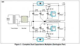
I don't know how many of you are using capacitance multipliers or ripple eaters with your JLH but perhaps you can help with this problem. I just lost the second set of pass devices in my capacitance multiplier and the failure mode was a bit insiduous. Specifically nothing was noticeable (the amplifier kept working) but I noticed when probing with my voltmeter that the regulation had been lost and the full filtered transformer voltage was now at the amplifier. Fortunately the amplifier did not seem to mind.
The design is basically the attached ESP design with the following modifications:
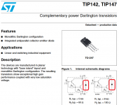
1. TIP142/TIP147
2. Omitted the 1N4007 diodes (as attached diodes are built into the TIP142/147)
3. Single RC stage (1k resistor and 2700 uF)
4. The 12k resistors are replaced with Zener diodes to limit the maximum output. (So more of a regulator than just a capacitance multiplier now.)
5. 2700 uF output capacitor (to help when used with class AB amplifiers)
The heatsink was not hot at all. Any suggestions on what might be causing the failures?
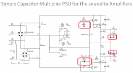
I looked at the Hifisonix ripple eater schematic and noticed that it has four more diodes. I assume these are additional protection diodes not found in the ESP design. (See attached.)
The design is basically the attached ESP design with the following modifications:
1. TIP142/TIP147
2. Omitted the 1N4007 diodes (as attached diodes are built into the TIP142/147)
3. Single RC stage (1k resistor and 2700 uF)
4. The 12k resistors are replaced with Zener diodes to limit the maximum output. (So more of a regulator than just a capacitance multiplier now.)
5. 2700 uF output capacitor (to help when used with class AB amplifiers)
The heatsink was not hot at all. Any suggestions on what might be causing the failures?
I looked at the Hifisonix ripple eater schematic and noticed that it has four more diodes. I assume these are additional protection diodes not found in the ESP design. (See attached.)
Attachments
With the 1000 Ohms and 2,700 uF into the base of the pass transistor I would have thought that the charging time was so long that the charging currents were relatively low.
Time constant 2.7 seconds
Rise time from 20% to 80% 3.78 seconds
Rise time from 10% to 90% 5.94 seconds
3dB cutoff frequency ~58.946275 millihertz
I was thinking more of discharge current on power off, such as discharging the 2,700 uF at the base of the pass transistor.
Time constant 2.7 seconds
Rise time from 20% to 80% 3.78 seconds
Rise time from 10% to 90% 5.94 seconds
3dB cutoff frequency ~58.946275 millihertz
I was thinking more of discharge current on power off, such as discharging the 2,700 uF at the base of the pass transistor.
Yes, that is a typical failure point. Lots of charge into the base=lots of amps out= maybe more than can handle. HOwever, it has to be initiated, such as a sudden heavy load. That tends not to happen if everything is wired up. The reverse diode (E-C) should not really be needed, as the voltage should fall first on the output if current is still drawn after switching off.
Old Post Office power supplies which used to be common (decades ago) used capacitor ripple filters and a Zener diode on the base (where your 12k is) but no capacitors on the base.
You might get an insight into the charging currents if you run a simulation with 50 (or 60) Hz AC input to the bridge and the capacitor initial conditions set to zero, with an appropriate load resistor on the output.
As a protection. you could add a base resistor (Darlingtons usually have a high gain that a moderate resistor can be used) and a transistor limiting the current on the output to some appropriate value, and possibly with a VI limiting resistor too.
Your point about the BC252 is that it is a low current device, then it's not very different from the BC559 type device. Many devices of that type were almost the same.
I'd expect the BC559 would perform as well.
Elektor once published a list of devices which were almost identical, covering BC184, BC214, BC257 etc. Quite why so many different device type names were registered is probably due to manufacturers wanting to differentiate themselves.
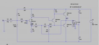
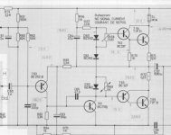
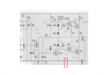
Regarding the circuit, is a classic Class AB design with Miller compensation and feedback from the output side of the output capacitor. I assume the short circuit highlighted below is not a short but a link that wanders off to another part of the circuit?
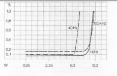
Feedback from the output side of the capacitor extends the bass response and was typically adopted when large capacitors (greater than 1mF) were uncommon or expensive and large. However, that comes at the expense of limiting the output power at those low frequencies because of charging-limited distortion.
The circuit could be improved in several respects.
I'd expect the BC559 would perform as well.
Elektor once published a list of devices which were almost identical, covering BC184, BC214, BC257 etc. Quite why so many different device type names were registered is probably due to manufacturers wanting to differentiate themselves.
Regarding the circuit, is a classic Class AB design with Miller compensation and feedback from the output side of the output capacitor. I assume the short circuit highlighted below is not a short but a link that wanders off to another part of the circuit?
Feedback from the output side of the capacitor extends the bass response and was typically adopted when large capacitors (greater than 1mF) were uncommon or expensive and large. However, that comes at the expense of limiting the output power at those low frequencies because of charging-limited distortion.
The circuit could be improved in several respects.
Attachments
Dual CV 30
Stereo Integrated Amplifier (1972)
Power output: 10 watts per channel into 4Ω (stereo)
Frequency response: 30Hz to 30kHz
Total harmonic distortion: 1%
Dual CV 30 Stereo Integrated Amplifier Manual | HiFi Engine
Replace the TiP3055 output transistors. Set the quiescent current to 1A. It turns out NJ1970 class A.
I don't know how many of you are using capacitance multipliers or ripple eaters with your JLH but perhaps you can help with this problem. I just lost the second set of pass devices in my capacitance multiplier and the failure mode was a bit insiduous. Specifically nothing was noticeable (the amplifier kept working) but I noticed when probing with my voltmeter that the regulation had been lost and the full filtered transformer voltage was now at the amplifier. Fortunately the amplifier did not seem to mind.
The design is basically the attached ESP design with the following modifications:
1. TIP142/TIP147
2. Omitted the 1N4007 diodes (as attached diodes are built into the TIP142/147)
3. Single RC stage (1k resistor and 2700 uF)
4. The 12k resistors are replaced with Zener diodes to limit the maximum output. (So more of a regulator than just a capacitance multiplier now.)
5. 2700 uF output capacitor (to help when used with class AB amplifiers)
The heatsink was not hot at all. Any suggestions on what might be causing the failures?
I looked at the Hifisonix ripple eater schematic and noticed that it has four more diodes. I assume these are additional protection diodes not found in the ESP design. (See attached.)
Hello Kozard, just seen this. The additional diodes are indeed protection, and also there to ensure the ripple eater cap is fully discharged, or discharges quickly, after you turn the power off. The diode across the series pass transistor is there in case the main reservoir caps for some reason discharge more quickly than the amplifier module caps, although I admit this is an unlikely scenario.
Since the series pass transistors drop about 1.5V across them when operating correctly, another trick or protect your ripple eater is to put three diodes in series across the collector emitter of the series pass device - anode to collector, cathode to emitter. If the series pass devices comes out of saturation, these diodes will conduct, limiting the power consumption of the series pass device. You must rate the diodes for the worst case continuous current draw of your load circuit.
Note carefully, if you use this technique, the soft start characteristic of the ripple eater will be sacrificed, but in most cases this is not an issue.
Your point about the BC252 is that it is a low current device, then it's not very different from the BC559 type device. Many devices of that type were almost the same.
I'd expect the BC559 would perform as well.
Elektor once published a list of devices which were almost identical, covering BC184, BC214, BC257 etc. Quite why so many different device type names were registered is probably due to manufacturers wanting to differentiate themselves.
Regarding the circuit, is a classic Class AB design with Miller compensation and feedback from the output side of the output capacitor. I assume the short circuit highlighted below is not a short but a link that wanders off to another part of the circuit?
Feedback from the output side of the capacitor extends the bass response and was typically adopted when large capacitors (greater than 1mF) were uncommon or expensive and large. However, that comes at the expense of limiting the output power at those low frequencies because of charging-limited distortion.
The circuit could be improved in several respects.
You are right about the power limiting at low frequencies. But with larger capacitor this type of feedback corrects its non linearity .
Attachments
Last edited:
Feedback from the output was usually implemented for improved bass response with a small capacitor and to correct capacitor distortion. I suspect modern caps intended for high frequency SMPS with low ESR and ESL will have lower distortion, and not require the feedback, but not seen any recent data on distortion measurements.
Probably because most amps are now direct coupled to the speaker.
Probably because most amps are now direct coupled to the speaker.
explained fairly well in the appropriate wikipedia pages. E.g. BC108 familyQuite why so many different device type names were registered is ..
Noise, power, voltage, case. All cause different part numbers
Class AB like that often will work in class A. If a switch mode PSU is used it can be an auxiliary current limiter. The ability to go into AB is preferred by Douglas Self in his class A designs. I won't say more because I feel that is a complete concept of a A+AB design except that done with care it might sound better than a JLH especially on transients. The PSU current might be upgradable when enough time has past to know it's thermally stable.
- Home
- Amplifiers
- Solid State
- JLH 10 Watt class A amplifier