Hello guys, need your advice again...")
I'm building this dual rail linear regulated power supply for a class A Hood
amplifier (I have ordered a kit - the version with 4 output transistors/channel). I have purchased almost all the parts for the PSU and now I try to figure out what kind of cooling I need for the diodes and for the regulator.
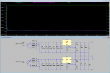
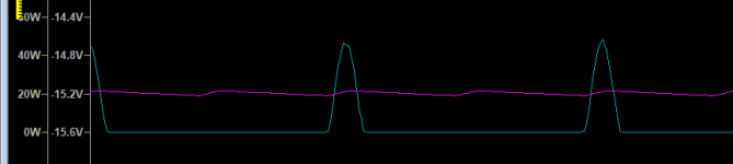
I have run the LTSpice simulation and I am quite puzzled by the results. Given an output current of ~4.5 Amps, the Power consumption on each diode is as much as 40W, while on the regulator is ~20W.
The diodes are MUR860 (not available in Spice so I have used a close match) and the regulator LT1083CP.
Given these figures, the radiator on each diode needs to be 3 deg/Watt and this is way bigger than I have expected.
The question is: am I missing something here? Do I really need this kind of cooling in normal working conditions? I was planning to use one cooler for each two diodes, placed back to back, but now I don't think this is a valid option...
Schematics and simulation data bellow:


Thank you,
Mihnea
I'm building this dual rail linear regulated power supply for a class A Hood
amplifier (I have ordered a kit - the version with 4 output transistors/channel). I have purchased almost all the parts for the PSU and now I try to figure out what kind of cooling I need for the diodes and for the regulator.
I have run the LTSpice simulation and I am quite puzzled by the results. Given an output current of ~4.5 Amps, the Power consumption on each diode is as much as 40W, while on the regulator is ~20W.
The diodes are MUR860 (not available in Spice so I have used a close match) and the regulator LT1083CP.
Given these figures, the radiator on each diode needs to be 3 deg/Watt and this is way bigger than I have expected.
The question is: am I missing something here? Do I really need this kind of cooling in normal working conditions? I was planning to use one cooler for each two diodes, placed back to back, but now I don't think this is a valid option...
Schematics and simulation data bellow:
Thank you,
Mihnea
Attachments
First thoughts - why not use a standard 25A bridge rectifier rather than 8A individual ones? (Easier to wire up, too). For mains (line) frequencies 50/60Hz you don't really need fast ones.
Secondly, you have no resistances in your circuit. Transformer windings add a bit of resistance. Without resistance, your capacitors (massive value, BTW) will charge at the rate limited only by the diodes. Reducing an average current to a number of short spikes increases the RMS value and hence dissipation.
So you probably don't need all that capacitance, at least on the input side.
Thank you guys for the fast reply!
@OldDIY - I am going to build two separate PSU, this is only for one channel.
@john_ellis - Thank you for the details. I am not going to lie to you, this is not my strong point, I am just a beginner. So if you can help me pick a proper bridge rectifier and show me where to place those resistances, I would be grateful.
I consider changing those caps at some points, I am just using them for now as I was able to get them for a good price. I realize that there are better options there.
Thank you,
Mihnea
Regarding your schematic and 100nf decoupling capacitors, take a look at this thread, quite interesting stuff, might wannabe make you redraw schematic.
paralleling film caps with electrolytic caps
And the thread, quasi modo bellringer, a simpel circuit that well makes psu ring and choose appropriate decoupling, this way it's done right.
https://www.google.com/url?sa=t&sou...FjAUegQIARAB&usg=AOvVaw0qlYS854IhRRHWSdTMU0mE
paralleling film caps with electrolytic caps
And the thread, quasi modo bellringer, a simpel circuit that well makes psu ring and choose appropriate decoupling, this way it's done right.
https://www.google.com/url?sa=t&sou...FjAUegQIARAB&usg=AOvVaw0qlYS854IhRRHWSdTMU0mE
Last edited:
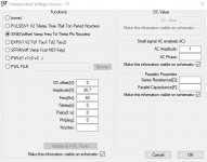
Further investigating I reached to the conclusion that the crazy values on the diodes are because I have added no resistance on the Voltage Source. This is something you have already told me and I did not get it right away.

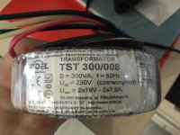
The issue is now that I am not sure what values should I use for Serial Resistance & Parallel Capacitance. I am using this transformer:

Also, maybe this is not the proper transformer for the job. I'm hoping to get clean 18V out of that.
Can you please help figure it out?
Thank you,
Mihnea
The issue is now that I am not sure what values should I use for Serial Resistance & Parallel Capacitance. I am using this transformer:
Also, maybe this is not the proper transformer for the job. I'm hoping to get clean 18V out of that.
Can you please help figure it out?
Thank you,
Mihnea
Attachments
Last edited:
The large capacity of the capacitors and the multi-stage CRC filtering will make it possible to do without a stabilizer. Place the most sounding capacitor in front of the amplifier.
For stereo, you will need two bipolar power supplies. With the help of additional diodes, you can make a power splitter.
For stereo, you will need two bipolar power supplies. With the help of additional diodes, you can make a power splitter.
Last edited:
Well, the 0.2K/W figure is about the best and is as Ian mentioned, Berquist silpad. Other silicone (filled with thermally conductive compounds or not) may well be worse.
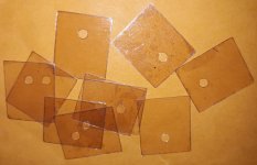
The images of some of the "mica" materials appear to be silicone. Mica is transparent, at least in the traditional types of insulator. That's why I am cautioning buying "mica" on the internet without checking its thermal resistance.
My mica arrived today and I stacked 10 together to measure with my digital calipers. I measured 0.78mm for the ten so 0.078mm each. Very close to the advertised specifications of 0.07mm. As close as I think I can measure.
They are 20mm x 25mm x 0.07mm Ebay Item 323761666123. 200pcs for US $7.42 which includes SpeedPAK shipping. A lifetime supply even with L20.5 and 8 per side.
I have attached a photo. They appear to be real mica and not the glued together dust version. I think they are quite good but I would like your expert opinion. In case this is judged to be a good price, thickness and quality here is the link if anyone else is looking. They have other sizes. I picked a bigger size that can be used with all of my output transistors.
200pcs Microwave Oven Mica Plates Sheets Repairing Part 20mm x 25mm x0.07mm | eBay
Attachments
Last edited:
mihneanu, the resistances I mentioned, just to make clear, are not external ones, but the internal resistances of the transformer windings. A typical 230/240V primary would be in the order of 2-3 ohms and the secondaries in approximately the ratio of the squares of the voltage, so 19V windings should be around .02 ohms but I'd anticipate a little higher, perhaps in the region of 0.05-0.1 ohms as the secondaries are usually wound over the primary (and therefore have a longer turn length). (and how thick the wire that was used- some manufacturers may push the resitance to minimise copper wire costs).
If you use a large capacitor with an additional resistor-capacitor filter, then for 50Hz a 10mF capacitor has an impedance of 0.3 ohms so a resistor of just 1 ohm will give you a ripple reduction of 1/6 (full wave rectification gives you 100Hz ripple) but will need to be able to dissipate 4W for 2A current, and 9W for 3A etc, so I'd certainly use a separate RC for each amplifier, even if you use a single bridge and first stage filter cap.You could use bigger resistors to attenuate the ripple further, but the power will go up in proportion too.
I generally use resistors rated at 2x power and under-run rather than use, say, a 5W resistor at 4W which may get hot (lower power resistors are physically smaller than higher power ones) and I'd also probably use metal clad ones mounted on a heatsink. Industrially there is a 50C limit which anything hotter needs to have a separate screen so it can't be touched while in use, and I believe that applies to domestic equipment as well, and is also something which I follow.
You could use two bridge rectifiers, one for each channel, and C-R-C filters on each as olddiy suggests or one bridge and C, with a separate R-C per channel.
Great! I honestly didn't hold much hope for finding mica pads this thin any more - not via Ebay, at least. Unfortunately, the seller is now all sold outMy mica arrived today and I stacked 10 together to measure with my digital calipers. I measured 0.78mm for the ten so 0.078mm each. Very close to the advertised specifications of 0.07mm......

I have been away from this thread for a while, but enjoying the PNP JLH daily with music. I still have not heard another amp that I liked better.
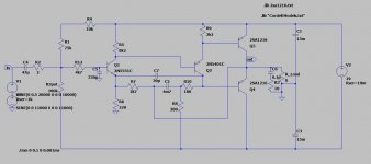
Anyway, I have been learning to simulate loop gain, and did a test on my JLH PNP model. It seems to be a little bit close to the limit on the phase margin at 35deg (even if I have not observed any oscillations before when testing it), so I tried some compensation on it. The placement of the cap is a bit odd(?) but seems to work. I avoided the 'speedup cap' over the feedback resistor since some advice against it. I can't see any added distortion at 20kHz with the compensation, and OLG seems to be constant to 20kHz too.
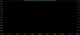
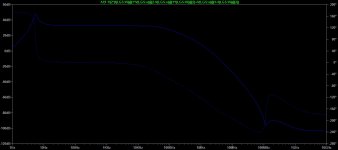
I attach some sim results and schematic, and hope somebody with more knowledge can comment on it.
(if phase in the text below is -99, the phase margin should be 180-99=81deg)
45pF
Measurement: phase_margin
step -1/(1-1/(2*(i(lgs:vi)@1*v(lgs:x)@2-v(lgs:x)@1*i(lgs:vi)@2)+v(lgs:x)@1+i(lgs:vi)@2)) at
1 (-1.81535e-005dB,-99.2802°) 3.3001e+006
2 (-1.81535e-005dB,-99.2802°) 3.3001e+006
Measurement: gain_margin
step -1/(1-1/(2*(i(lgs:vi)@1*v(lgs:x)@2-v(lgs:x)@1*i(lgs:vi)@2)+v(lgs:x)@1+i(lgs:vi)@2)) at
1 (32.6581dB,5.26793e-008°) 225.605
2 (32.6581dB,5.26793e-008°) 225.605
30pF
Measurement: phase_margin
step -1/(1-1/(2*(i(lgs:vi)@1*v(lgs:x)@2-v(lgs:x)@1*i(lgs:vi)@2)+v(lgs:x)@1+i(lgs:vi)@2)) at
1 (-5.51484e-006dB,-104.984°) 2.49894e+006
2 (-5.51484e-006dB,-104.984°) 2.49894e+006
Measurement: gain_margin
step -1/(1-1/(2*(i(lgs:vi)@1*v(lgs:x)@2-v(lgs:x)@1*i(lgs:vi)@2)+v(lgs:x)@1+i(lgs:vi)@2)) at
1 (32.6582dB,1.51565e-008°) 224.227
2 (32.6582dB,1.51565e-008°) 224.227
15pF
Measurement: phase_margin
step -1/(1-1/(2*(i(lgs:vi)@1*v(lgs:x)@2-v(lgs:x)@1*i(lgs:vi)@2)+v(lgs:x)@1+i(lgs:vi)@2)) at
1 (-1.60138e-005dB,-121.256°) 2.03223e+006
2 (-1.60138e-005dB,-121.256°) 2.03223e+006
Measurement: gain_margin
step -1/(1-1/(2*(i(lgs:vi)@1*v(lgs:x)@2-v(lgs:x)@1*i(lgs:vi)@2)+v(lgs:x)@1+i(lgs:vi)@2)) at
1 (32.6582dB,3.91336e-008°) 222.889
2 (32.6582dB,3.91336e-008°) 222.889
0pF(no compensation, as it is now)
Measurement: phase_margin
step -1/(1-1/(2*(i(lgs:vi)@1*v(lgs:x)@2-v(lgs:x)@1*i(lgs:vi)@2)+v(lgs:x)@1+i(lgs:vi)@2)) at
1 (-0.00012307dB,-145.445°) 1.89806e+006
2 (-0.00012307dB,-145.445°) 1.89806e+006
Measurement: gain_margin
step -1/(1-1/(2*(i(lgs:vi)@1*v(lgs:x)@2-v(lgs:x)@1*i(lgs:vi)@2)+v(lgs:x)@1+i(lgs:vi)@2)) at
1 (32.6583dB,6.25893e-008°) 221.574
2 (32.6583dB,6.25893e-008°) 221.574
Sorry about the quality of the graphs! The LF peak is due to the floating ground I think.
Anyway, I have been learning to simulate loop gain, and did a test on my JLH PNP model. It seems to be a little bit close to the limit on the phase margin at 35deg (even if I have not observed any oscillations before when testing it), so I tried some compensation on it. The placement of the cap is a bit odd(?) but seems to work. I avoided the 'speedup cap' over the feedback resistor since some advice against it. I can't see any added distortion at 20kHz with the compensation, and OLG seems to be constant to 20kHz too.
I attach some sim results and schematic, and hope somebody with more knowledge can comment on it.
(if phase in the text below is -99, the phase margin should be 180-99=81deg)
45pF
Measurement: phase_margin
step -1/(1-1/(2*(i(lgs:vi)@1*v(lgs:x)@2-v(lgs:x)@1*i(lgs:vi)@2)+v(lgs:x)@1+i(lgs:vi)@2)) at
1 (-1.81535e-005dB,-99.2802°) 3.3001e+006
2 (-1.81535e-005dB,-99.2802°) 3.3001e+006
Measurement: gain_margin
step -1/(1-1/(2*(i(lgs:vi)@1*v(lgs:x)@2-v(lgs:x)@1*i(lgs:vi)@2)+v(lgs:x)@1+i(lgs:vi)@2)) at
1 (32.6581dB,5.26793e-008°) 225.605
2 (32.6581dB,5.26793e-008°) 225.605
30pF
Measurement: phase_margin
step -1/(1-1/(2*(i(lgs:vi)@1*v(lgs:x)@2-v(lgs:x)@1*i(lgs:vi)@2)+v(lgs:x)@1+i(lgs:vi)@2)) at
1 (-5.51484e-006dB,-104.984°) 2.49894e+006
2 (-5.51484e-006dB,-104.984°) 2.49894e+006
Measurement: gain_margin
step -1/(1-1/(2*(i(lgs:vi)@1*v(lgs:x)@2-v(lgs:x)@1*i(lgs:vi)@2)+v(lgs:x)@1+i(lgs:vi)@2)) at
1 (32.6582dB,1.51565e-008°) 224.227
2 (32.6582dB,1.51565e-008°) 224.227
15pF
Measurement: phase_margin
step -1/(1-1/(2*(i(lgs:vi)@1*v(lgs:x)@2-v(lgs:x)@1*i(lgs:vi)@2)+v(lgs:x)@1+i(lgs:vi)@2)) at
1 (-1.60138e-005dB,-121.256°) 2.03223e+006
2 (-1.60138e-005dB,-121.256°) 2.03223e+006
Measurement: gain_margin
step -1/(1-1/(2*(i(lgs:vi)@1*v(lgs:x)@2-v(lgs:x)@1*i(lgs:vi)@2)+v(lgs:x)@1+i(lgs:vi)@2)) at
1 (32.6582dB,3.91336e-008°) 222.889
2 (32.6582dB,3.91336e-008°) 222.889
0pF(no compensation, as it is now)
Measurement: phase_margin
step -1/(1-1/(2*(i(lgs:vi)@1*v(lgs:x)@2-v(lgs:x)@1*i(lgs:vi)@2)+v(lgs:x)@1+i(lgs:vi)@2)) at
1 (-0.00012307dB,-145.445°) 1.89806e+006
2 (-0.00012307dB,-145.445°) 1.89806e+006
Measurement: gain_margin
step -1/(1-1/(2*(i(lgs:vi)@1*v(lgs:x)@2-v(lgs:x)@1*i(lgs:vi)@2)+v(lgs:x)@1+i(lgs:vi)@2)) at
1 (32.6583dB,6.25893e-008°) 221.574
2 (32.6583dB,6.25893e-008°) 221.574
Sorry about the quality of the graphs! The LF peak is due to the floating ground I think.
Attachments
Last edited:
C7 is an interesting way to do it. In a quest to get my version working I used 33 pF base to collector Q2. It wasn't a great plan on my part ( NPN version, BC337/327-40 and 2N2055 India ). I did have marginal stability problems without something. I only had 33 pF, I regret not trying 2 x 33 pF as 16.5 pF.
Interesting that you choose to use the floating ground. As a quick simulation (different models) I get with zero pF a UGLF of 3.3MHz, phase margin ~40 degrees and gain margin about 30dB (gain 0.039). With 33pF, UGLF 6.9MHz, phase margin 86 degrees and gain margin not observed as my sim. stopped at 100MHz. So better than 30dB.
Looks like your simulations are about right. Your compensation connection is not "unusual" as JLH tended to use it in his circuits when he added compensation (but not his recommended additions to this particular circuit!). It provides phase lead correction rather than phase lag.
33pF was the value I had used to compensate one of my JLH builds using high speed transistors.
Adding it where you have shown is optimum. You can add it across the feedback resistor, but that makes the circuit more sensitive to loading (output inductors may be needed etc)
More of a concern is the large LF spike. My sim shows UGLF below 1Hz but +180 degrees phase shift, so that needs compensation to avoid what used to be called "motorboating" or LF oscillations, I suspect. When I built one of these arrangements many years ago, I did not get continuous oscillations but every LF transient came with a free subsonic signal that the loudspeaker cones did not like. My solution at the time was to use big decoupling on the input bias chain, but I've not trusted this arrangement in amps I actually use now!
Probably don't need the input filter unless you need to suppress RF, but if the source impedance is high, I 'd still add a capacitor to keep the impedance low at HF as the stability depends on it.
Last edited:
I remember JLH saying something about this. He disliked the method I used. I remember JLH saying an even better way of doing it must be possible. I have no idea if he found it. His speculation seemed if I remember correctly using the output stage to input due to vast current available. Again if memory is right he didn't think phase shift too complex a problem.
Your approach was the standard Miller compensation. I don't recall what JLH wrote about this but it is clear he preferred a different approach. In his -I think - 70W Class AB amp which originally used 2N3442's (anyone who thinks the 2N3055H was bad (not many, at the time, I suggest) the 2N3442 was worse - 200kHz fT for audio???) he used phase lead compensation. Of course to be fair he soon changed the devices to BD somethings at 10MHz. He didn't, as far as I recall either, use this option in his 10W Class A but a combination of three elements which he said "were all or none".
I have found phase lead compensation, as Rallyfinnen indicates as well, that phase lead works particularly when used around only two stages. As did Bailey in his '68 design - the first time I'd seen it.
I have found phase lead compensation, as Rallyfinnen indicates as well, that phase lead works particularly when used around only two stages. As did Bailey in his '68 design - the first time I'd seen it.
These were various ideas that many may not know.
A Paul Kemble web page - JLH mosfet amplifiers.
A Paul Kemble web page - JLH mosfet amplifiers.
- Home
- Amplifiers
- Solid State
- JLH 10 Watt class A amplifier