New owner of Yaqin SD-CD3. Can I remove the aluminum guard around the tubes or will that cause the tube sockets to come loose ?
Yes you can take it off, no problem. Looks better without. It is attached to the frame with three bolds. The tube sockets are only attached to the pcb and the pcb is attached to the frame with seperate bolds.

Sjef.
I agree with you about the Yaqin CD3 buffer needing the addition of bleeding resistors.While setting up my system I experienced a very loud buzz while changing interconnects even after powering everything down and waiting a few minutes.
Luckily I read your post before hand and was ready for something to happen.
I thought I may have fried a component but luckily I did not. I will be installing the bleeder resistors ASAP.
Until then, If I’m changing interconnects I will disconnect the power cords on my equipment.
That seems to help as a temporary solution.
Thanks,
AmpUtator.
Yaqin CD3 Tube Buffer bleeders
Hi all, a new member here. The info from this thread has been of great value. I need some help regarding what value resistors are required for bleed resistors on the power caps (already sorted for the input & output bleed resistors). Any info would help. I'm also a bit confused as to how it is implemented. Some photos show the implementation of two resistors across the first cap whereas some show it as one per cap (bridged). Not having a great deal of experience with this, your help would be of great value.
Thanks for this thread, added bleed resistors to one of these before putting it into a friends system.
Hi all, a new member here. The info from this thread has been of great value. I need some help regarding what value resistors are required for bleed resistors on the power caps (already sorted for the input & output bleed resistors). Any info would help. I'm also a bit confused as to how it is implemented. Some photos show the implementation of two resistors across the first cap whereas some show it as one per cap (bridged). Not having a great deal of experience with this, your help would be of great value.
Yaqin CD - more details before following suggestions
#1) the bleeder resistors for input & output (480KOhm & 120 KOhm) that I can get come in values of half watt or 1 watt - will it make a difference which I use?
#2) what value resistors did you use as bleeders/ bridge/bypass on the 2 x power caps?
Any help is much appreciated.
#1) the bleeder resistors for input & output (480KOhm & 120 KOhm) that I can get come in values of half watt or 1 watt - will it make a difference which I use?
#2) what value resistors did you use as bleeders/ bridge/bypass on the 2 x power caps?
Any help is much appreciated.
1) Either will work fine but the 1/2W may (emphasis on may) take up a little less room and be easier to fit than the 1W.#1) the bleeder resistors for input & output (480KOhm & 120 KOhm) that I can get come in values of half watt or 1 watt - will it make a difference which I use?
#2) what value resistors did you use as bleeders/ bridge/bypass on the 2 x power caps?
Any help is much appreciated.
2) I used a single 220K/2W resistor across C5 only. C6 has a series 6.8K between the plus posts of the two caps so it will drain thru the 6.8K and then the 220K. No need for a 2nd resistor across C6. I used 1M across the inputs and 100K across the outputs.
I just got it about a month ago. It was completely stock when I took delivery of it. It came with a pair of Baldwin 6SN7GTB tubes that I don't know anything about. Still up in the air about swapping them out for something else. I've seen a lot of folks have swapped out the film caps. I may or may not try that mod later on down the road. As of now I'm happy with the buffer's performance. I ended up placing it between my pre and power amps. My Magnepans seem to image even better now. The soundstage seems wider and the instruments in that soundstage seem better defined now.
Nice! I believe swapping tubes could make a difference, based on my experience swapping tubes out on systems I had earlier. I haven't received mine yet. It was shipped a while ago and should hopefully arrive soon. I am relieved to hear it has made a difference for you. I was getting worried after having read some (a few) of the rather negative and off-putting comments regarding this unit and that it does absolutely nothing (placebo?). I am determined to give it a fair try. I will be doing the film cap mods fairly quickly (already ordering those). Already bought some replacement tubes (6SN7GT - Sylvanias and RCAs). The first thing I will do is the resistors - just to protect my other gear. I owned the Yaqin MC-13s tube amp a few years ago and spent quite a few dollars on tube rolling. It was a good amp for the price but I lost interest in it. Just didn't quite get the sound I was after. I found it somewhat sterile sounding. I have a tube DAC , which has been modded (film caps) and a tube phone pre-amp (Parks Audio Budgie). If you do decide to do the mods and tube rolling, let me know your impressions. It would be excellent to share experiences. I will do the same. Thanks again!
Hey new member here also.
I will be taking delivery of this pre amp next week and wondered if anyone could offer links to upgraded caps and the correct bleed resistors and where they need to go?
Or, if there is an ‘upgrade service’ provided where I can send in the amp to get new caps and the bleed resistor.
I’m smart enough to research and understand what needs to be done but not skilled enough to do the soldering etc.
Appreciate any advice, thanks everyone")
I will be taking delivery of this pre amp next week and wondered if anyone could offer links to upgraded caps and the correct bleed resistors and where they need to go?
Or, if there is an ‘upgrade service’ provided where I can send in the amp to get new caps and the bleed resistor.
I’m smart enough to research and understand what needs to be done but not skilled enough to do the soldering etc.
Appreciate any advice, thanks everyone
I’m sure no one is reading this, but if someone is I’d like some advice if possible please?
I have read that 2 x 1uf Caps instead of 4x0.47uf caps is a better option due to costs and time invested. I also understand that they are in parallel. So with that in mind, do I simply solder in the new 1uf caps in ‘c2’ and ‘c4’ and leave it at that, or must I bridge the “gaps” left my the missing 2 0.47 caps with a wire (on the correct side of the terminals to each other) and same for the other side?
If someone had a picture of this completed it would be amazing.
Anyway, I will be spending much time learning to solder etc before I undertake this work, but this is my end goal.
Appreciate your expertise
Replace C2a and C4a with 1.0uf caps. Leave C2b and C4b empty. Do NOT replace them with a jumper. Doing so will short caps C2a and C4a out of the circuit.
Oh my, thanks ever so much for responding
you’re awesome.
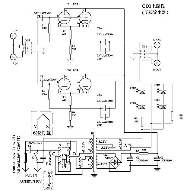
One more bit of info regarding the SD-CD3's schematic. All the schematics I've seen show the left side of C2a&b and C4a&b connected to the junction between resistors R2&R3 (left channel) and R5&R6 (right channel). The left side of caps C2&4 should be shown connected to the junction between pins 3&6 of each tube and the top of resistors R2 (left) and R5 (right).
Along with that I would recommend the following...
* Add a 1M resistor across each input jack.
* Add a 100K resistor across each output jack.
* Add a 220K/2W power resistor across the leads of filter cap C5. This will provide a discharge path to ground for both filter caps.
Along with that I would recommend the following...
* Add a 1M resistor across each input jack.
* Add a 100K resistor across each output jack.
* Add a 220K/2W power resistor across the leads of filter cap C5. This will provide a discharge path to ground for both filter caps.
One more bit of info regarding the SD-CD3's schematic. All the schematics I've seen show the left side of C2a&b and C4a&b connected to the junction between resistors R2&R3 (left channel) and R5&R6 (right channel). The left side of caps C2&4 should be shown connected to the junction between pins 3&6 of each tube and the top of resistors R2 (left) and R5 (right).
Along with that I would recommend the following...
* Add a 1M resistor across each input jack.
* Add a 100K resistor across each output jack.
* Add a 220K/2W power resistor across the leads of filter cap C5. This will provide a discharge path to ground for both filter caps.
Again, invaluable information, thanks so much.
I have got some 100k resistors for the output and 300k for the input as per a few comments further up. However I suppose I’d rather follow your instructions assuming this information is somewhat newer than the info from a few years ago.
Regards the 220k/2W across the ‘leads of filter cap c5’. What do you mean ‘accords the leads’?
I know I’m asking noob questions but rest assured I will be experienced with practice boards + resistors etc before I dare go near the real one.
Thank you very much!

- Home
- Source & Line
- Analog Line Level
- Yaqin SD-CD3 Tube Buffer - upgrading caps