In standard form, the source impedance needs to be no more than 2K which suits many preamps, including JLH's various designs, even this buffer: https://www.diyaudio.com/forums/att...-homage-john-linsley-hood-discrete-buffer-jpg
Accordingly, a simple 10K voltage divider pot. can sound very good at lower levels but not so good at higher volume settings. I'm aware that the amp. doesn't need a preamp for line level sources but there is often a sweet spot with just the basic amplifier and pot. that inclines us to listen in a restricted volume range. Then a buffer or preamp of some description becomes an asset.
Accordingly, a simple 10K voltage divider pot. can sound very good at lower levels but not so good at higher volume settings. I'm aware that the amp. doesn't need a preamp for line level sources but there is often a sweet spot with just the basic amplifier and pot. that inclines us to listen in a restricted volume range. Then a buffer or preamp of some description becomes an asset.
Try a 100pF capacitor across the input first. If that solves the problem, I'd expore smaller values.
If that works but you loose treble you could add a JFET buffer but that might increase distortion. Might be OK with a PNP gain enhancement (wired like a CFP stage) and/or a constant current source to minimise current variation.
Well right now I have 100 pF across the input but in series with 68 Ohms. I still have the inductor on the output along with a Zobel. Right now it sounds pretty good. But I fear I am working on a new Rabbit Hole:
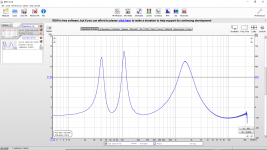
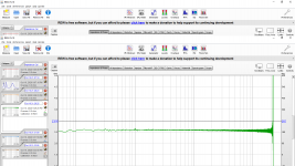
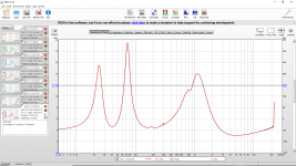
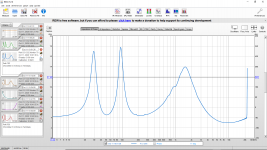
My test bench speakers are a pair of Polk CS1 speakers. Each time I have increased the bias current (first 1.0A, then 1.2A, and now 1.5A, all at 24V) it sounds like it is improving. So I asked if these speakers really are 8 Ohms as claimed. As a result today I tried to measure the Polk CS1 impedance and I get 4.3 Ohms but with huge spikes to 16 Ohms.
Does this look right? (Result attached.) I have never measured speaker impedance before. I am using REW and an 8 Ohm sense resistor. Clearly this is important for a JLH amplifier.
Attachments
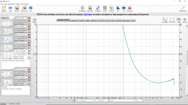
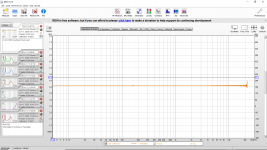
By the way I measured test load resistors with REW to try to make sure my measurements were valid. They seem to be ok for a 1/4W 10 Ohm Metal Film resistor and (8, 4 and 2 Ohm) 100W test load resistors. (Attached.)
I guess I need to re-bias my JLH and increase the heat sinks.
I guess I need to re-bias my JLH and increase the heat sinks.
Attachments
-
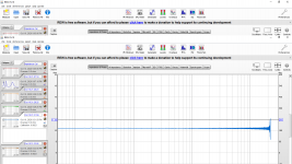 20201010 REW Speaker Impedance Test 10 Ohm Quarter Watt Metal Film Resistor.png151.9 KB · Views: 335
 -
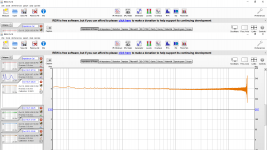 20201010 REW Speaker Impedance Test 8 Ohm 100W Resistor.png154.5 KB · Views: 326
 -
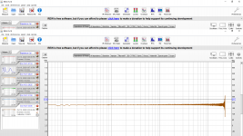 20201010 REW Speaker Impedance Test 4 Ohm 100W Resistor.png157.1 KB · Views: 278
 -
 20201010 REW Speaker Impedance Test 2 Ohm 100W Resistor.png155.6 KB · Views: 270
That's not unlike many ported (bass reflex) designs and your method looks good - nice work. A CSi centre speaker model isn't what I'd choose for bass reproduction but is probably fine for emphasizing spatial effects and musical details you might like to hear and also makes it suitable for investigating audiophile sound qualities.
Like most HT centre speakers, the frequency range is somewhat limited to those we use to identify the direction from which a sound is coming. The spec. states a 55-25,000 Hz range but not the sensitivity variation within it but by design, I'd expect it sound stronger in the mid-high range.
Like most HT centre speakers, the frequency range is somewhat limited to those we use to identify the direction from which a sound is coming. The spec. states a 55-25,000 Hz range but not the sensitivity variation within it but by design, I'd expect it sound stronger in the mid-high range.
BTW, since there is no useful mean speaker impedance value that could be applied to music program, the nominal speaker impedance on which the bias current is based, is not taken to be the minimum speaker impedance. Though the measured minimum shown on the graph is about 4 ohms, it would typically be quoted as a value closer to that of the whole audio program spectrum. In this case, I'd say 6R would be typical and happens to be the standard spec for all consumer HT and audio speakers now, whatever nonsense the label says.
As far as the JLH amplifier is concerned, I wouldn't rush into increasing bias current much at all - that mostly just increases heat dissipation problems. I would check for an abrupt rise in distortion artefacts by FFT scan but again, that usually means a 'scope.
As far as the JLH amplifier is concerned, I wouldn't rush into increasing bias current much at all - that mostly just increases heat dissipation problems. I would check for an abrupt rise in distortion artefacts by FFT scan but again, that usually means a 'scope.
as pointed out by others above, speakers have considerably varying impedances. I've always taken 5 ohms as a nominal low limit for an 8 ohm speaker, and several small 8 ohm speakers measured about 6 ohms D.C.. The coil inductance has a large part in the impedance characteristic, but acoustic effects certainly change across the audio band.
It could be that a 4 ohm limit means that the amplifier is clipping prematurely. A 1A standing current should allow 2A peak output but into 4 ohms will generate "only" 8W instead of 16 into 8 ohms. I wonder if a peak indicator might help identify the problem. A circuit which may help with that is attached.
It could be that the amplifier is breaking into oscillations under certain load conditions.
That needs an investigation and the Tian stability checks run at least in simulation. May need a larger compensation capacitor than 47pF, you could try 100 or 220pF, but too large and it may cause problems again.
It could be that a 4 ohm limit means that the amplifier is clipping prematurely. A 1A standing current should allow 2A peak output but into 4 ohms will generate "only" 8W instead of 16 into 8 ohms. I wonder if a peak indicator might help identify the problem. A circuit which may help with that is attached.
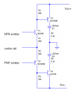
Since I am using a single supply mini1969 I did a quick rearrangement of the schematic (attached). Do you think this will work as a clip detector for the upper and lower NPN's in the mini1969 JLH (schematic attached)? Do you see any mistakes?
Attachments
Today I improved the cables and calibration with lower resistances and entry of the test lead resistance.
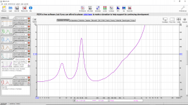
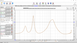
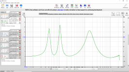
In case it is helpful for anyone else with a JLH or other Class A amplifier I have enclosed REW speaker impedance measurements for the Polk CS1, CS2, Monitor 70 and R50.
In case it is helpful for anyone else with a JLH or other Class A amplifier I have enclosed REW speaker impedance measurements for the Polk CS1, CS2, Monitor 70 and R50.
Attachments
-
 20201011 REW Speaker Impedance Test Polk R50.png157.4 KB · Views: 57
 -
 20201011 REW Speaker Impedance Test Polk Monitor 70 Bi-Wire Upper Terminals.png142.6 KB · Views: 55
 -
 20201011 REW Speaker Impedance Test Polk Monitor 70 Bi-Wire Lower Terminals.png168.4 KB · Views: 48
 -
 20201011 REW Speaker Impedance Test Polk Monitor 70.png157.9 KB · Views: 58
 -
 20201011 REW Speaker Impedance Test Polk CS2.png160.6 KB · Views: 347
 -
 20201011 REW Speaker Impedance Test Polk CS1.png159.5 KB · Views: 363
 -
 20201011 REW Speaker Impedance Test 4 Ohm 100W Resistor.png162.6 KB · Views: 390
Last edited:
")
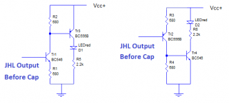
Think I posted this in the wrong thread. the idea was to monitor the current across a sense resistor. Your rearrangement would work if you add a suitable resistor in the collector of each NPN. To light at 2A the resistance will need to be about 0.33 ohms. For the upper device the connection is between the power rail and collector/sense resistor junction and for the lower device the PNP should be connected to the centre rail and sense resistor. For voltages greater than about 40V Vcc change the devices to BC546/BC556 or 2N5551/2N5401 or similar.
Thanks for that contribution, John. Perhaps it's the type of sensing device I should have used for monitoring or at least experimented with long ago. A dumb question though; would there be any hysteresis in switching the LEDs? A flicker will probably be more visible that a proportional glow with each event and might be a good thing.with attachment
Last edited:
Ian, LEDs are pretty fast. The only things delaying any turn off is charge storage in the bipolars (<<1us except perhaps power devices or saturated ones) and in the LED, but the LED tends to be quicker as they are designed to recombine electrons and holes in the active regions, which disappear quickly.
The only way to extend the LED light would be to add some sort of diode/resistor/capacitor filtering circuit so that the cap charges quickly but keeps the LED on longer, perhaps using another transistor to buffer the cap voltage.
You would see the LED light up if the amp repeatedly turned it on as with a continuous signal. It would be possible, I think, to miss a single event unless pulsed with a much higher current - and while it is tempting, that may fuse the bond wires or LED and could lead to damage if the pulse extended to long times (>ms perhaps).
I would appreciate advice/suggestions on an appropriate pre-amp (or just a buffer) to pair with the mini1969 JLH.
I am trying to weight the pros and cons of the following options:
1. Just put a 5532 or 4580 inverting/-1 buffer after my 50k Alps RK27.
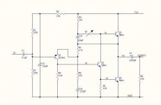
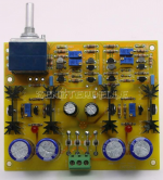
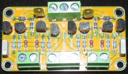
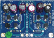
2. Diamond Buffer 2SA992 2SC1845 (Photo & schematic attached) after my 50k Alps RK27.
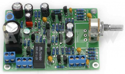
3. 2SK246 2SJ103 C2240 A970 JFET Input Cascoded Buffer Preamp (Photo & schematic attached) after my 50k Alps RK27.
4. NAIM NAC42.5 Preamplifier (Photo attached)
5. Class A FET Preamplifier JC-2 (Photo attached)
I am trying to weight the pros and cons of the following options:
1. Just put a 5532 or 4580 inverting/-1 buffer after my 50k Alps RK27.
2. Diamond Buffer 2SA992 2SC1845 (Photo & schematic attached) after my 50k Alps RK27.
3. 2SK246 2SJ103 C2240 A970 JFET Input Cascoded Buffer Preamp (Photo & schematic attached) after my 50k Alps RK27.
4. NAIM NAC42.5 Preamplifier (Photo attached)
5. Class A FET Preamplifier JC-2 (Photo attached)
Attachments
-
 Class A FET Preamplifier JC-2.png792.2 KB · Views: 102
 -
 NAIM NAC42.5 Preamplifier.png584.8 KB · Views: 144
 -
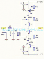 2SK246 2SJ103 C2240 A970 JFET Input Cascoded Buffer Preamp Schematic.png108.2 KB · Views: 145
 -
 2SK246 2SJ103 C2240 A970 JFET Input Cascoded Buffer Preamp.png514.5 KB · Views: 162
 -
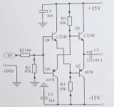 Diamond Buffer 2SA992 2SC1845 Schematic.png168.8 KB · Views: 168
 -
 Diamond Buffer 2SA992 2SC1845.png735 KB · Views: 118
I'd think that the diamond buffer would work well. Though I would be tempted to use lower current for reduced noise, but that depends on the loading required. The FET buffer probably has higher distortion if the FETs aren't matched, and matching complementary FETs might be difficult. I also would imagine that the output voltage could be offset from zero if they were not matched, worse than the BJT design, and would also need an output capacitor. Probably with positive to output like the BJT if the Vt and/or gain of the N channel is greater than the P.
Are the FETs still available?
Are the FETs still available?
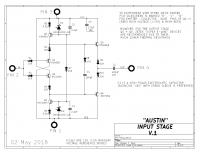
Another Diamond Buffer circuit is the "Austin" input stage daughter card for the First Watt power amp called M2x. Schematic below. Quite a few diyAudio members have built and are listening to "Austin". It's one of the PCBs the diyAudio Store ships you when you buy the M2x power amp board-set.
Yes, it's AC coupled.
_
Yes, it's AC coupled.
_
Attachments
I'd think that the diamond buffer would work well. Though I would be tempted to use lower current for reduced noise, but that depends on the loading required.
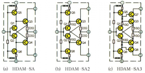
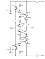
When I was reading about Diamond Buffer variants today I came across the series of HDAM circuits (attached screen shot) and then the attached version from an Apex MM preamp (second attached screen shot).
I assume the main purpose of the improvements in the current sources is to improve the linearity?
I have KSA992 and KSC1845 from Mouser so I could make pretty much any of the variations. Maybe I go all the way to the most complex?
I think I will like this pre-amp because of the similarity to the MA9S2 amplifier which I quite like, so perhaps worth the effort.
The FET buffer probably has higher distortion if the FETs aren't matched, and matching complementary FETs might be difficult. I also would imagine that the output voltage could be offset from zero if they were not matched, worse than the BJT design, and would also need an output capacitor. Probably with positive to output like the BJT if the Vt and/or gain of the N channel is greater than the P.
Are the FETs still available?
I doubt they are available, yet the kits ship with something. Not sure what that something actually is.
Attachments
Unless you have the cash to buy whatever spec. JFETs you like from specialist manufacturers of obsolete semis like Linear Systems or Central Semi, I'd leave T092 JFET designs alone. Using unbranded, fake or poor copies of the originals just doesn't make sense since you can wind up with too few of the FET benefits to be worthwhile.
We could argue that something we listened to and liked was actually built with fake parts or that in our application, the specification isn't at all critical but unless the seller has the same as previous source and quality semis, can you really expect the same performance next time?
Personally, I'd much rather take risks with bipolar transistors when playing with complex gain blocks like that HDAM circuit. It's fun and the results can be reliable, since the semis are cheap and still available in cut tape form which more or less ensures similar qualities between sequential parts from the same wafer.
- Home
- Amplifiers
- Solid State
- JLH 10 Watt class A amplifier