Hi Pyramid
Answers to your questions:-
Q1 - You have the correct waveform on the even pins of U5? - YES all pins with correct waveform.
Q2 - DC voltages on the outputs (0, 90, 120 & 240) when the SG4 is in standby?
Just to clarify, I was only using the 0 deg output, so I did not initially install the resistors and caps for the other outputs.
I have now installed these resistors and caps and found the following:-
0 = 0vdc
90 = 2.63vdc
120 = 2.63vdc
240 = 2.63vdc
Checked 0deg output on U2 pin14 = 2.6vdc, So checked and found a problem with the solder pad on 0deg output.
This solder joint and pad looked good but it was an open circuit.
Now all outputs good.
I just wish I had installed all the resistors & caps for the unused outputs, I think I would have spotted the problem earlier.
A big Thank you goes to Pyramid and Ralph for your advice, I think without your help I would have given up and thrown the pcb in the bin.
Hi guys,
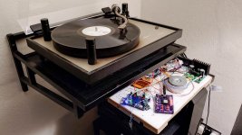
Clocking in again, just an update, still didn't manage to power up my SG4 using my Class D amp 7812 regulator. This is left off from post #908. But anyway once the movement restriction order ends, I'll be bringing in my friend whom has a scope to see what can be done.
Right now it's being powered by a wal-wart.
Right now, am working on replacing the thorens motor with an Allied Motion 31813 motor.
datasheet 9904 111 31813 (CROP)
It seems to work very very well. (i'm still working on getting a housing with a thrust bearing holder as well as a new spindle 3d printed and machined out). This motor is so much better than my old thorens motor. I realize the old thorens motor has quite a lot of play, and I suppose it does not have a very good bushing for radial force (belt pull). and that is the reason why the motor speed is unstable.
Compared to the 31813 motor? the 31813 is so much better. They both have about the same amount of vibration noise.
I have 2 quick questions.. Sorry for being so long winded.
1. Referring to link posted above, on the second page at the bottom, there was a suggestion to install 2 trimmer in series to the Red and Blue wire to electrically balance the motor. I wonder if anyone could provide any guidance as to how to electrically balance this motor in order to achieve optimum level of motor vibration? (I'm sorry if this is a wrong place to ask this, but please let me know where should i post it if this is not where it belongs).
2. With the SG4 powering the 31813 motor, would this motor benefit from any of the additional Linn power supply line up? i.e. valhalla etc?
Thanks!
1. Referring to link posted above, on the second page at the bottom, there was a suggestion to install 2 trimmer in series to the Red and Blue wire to electrically balance the motor. I wonder if anyone could provide any guidance as to how to electrically balance this motor in order to achieve optimum level of motor vibration? (I'm sorry if this is a wrong place to ask this, but please let me know where should i post it if this is not where it belongs).
Adjust one trimmer at a time while holding the motor in-hand for lowest vibration or using a stethoscope on the plinth.
2. With the SG4 powering the 31813 motor, would this motor benefit from any of the additional Linn power supply line up? i.e. valhalla etc?
No; running it dual phase will be the equivalent of using the Linn Lingo which is their SOTA power supply.
Adjust one trimmer at a time while holding the motor in-hand for lowest vibration or using a stethoscope on the plinth.
Ahh alright! In that case, would this work? 3296W-1-103 Bourns | Mouser Malaysia
or do i have to look for a trimmer that is able to handle more than 1.8W since it's a 1.8W motor? Which I think can be quite difficult to find. Also I notice that the wiring for the coil balance trimmers are direction agnostic (does not indicate CW or CCW), I'm assuming here when the motor is electrically balance, it is able to spin either direction with least vibration hence it does not matter?
No; running it dual phase will be the equivalent of using the Linn Lingo which is their SOTA power supply.
Ahh okay. Apologies if my understanding is bad. From my understanding, these motors uses a capacitor to invert the phase to drive these AC Synchronous motor. if running with SG4 means i'm running it dual phase, does that mean that I can actually forgo the capacitor (i,e leave the 0.22uF capacitor out)?
The trimmer will only change the current to the motor by a small amount, so it should be a fraction of the winding's resistance; 1.8W would imply a winding of ~7.3K so a 500Ω or 1KΩ trimmer would be more appropriate. The power dissipated by the pot would be 1/7 or 1/14 of the winding so 1/2W should be plenty. I would start with just one pot on the 2nd phase.
The motors normally use a cap to create a second phase ~90° from the primary winding, but the SG4 has the ability to generate both phases, is more accurate and is adjustable. It will also require a second amp, but you can eliminate the phase cap.
The motors normally use a cap to create a second phase ~90° from the primary winding, but the SG4 has the ability to generate both phases, is more accurate and is adjustable. It will also require a second amp, but you can eliminate the phase cap.
The trimmer will only change the current to the motor by a small amount, so it should be a fraction of the winding's resistance; 1.8W would imply a winding of ~7.3K so a 500Ω or 1KΩ trimmer would be more appropriate. The power dissipated by the pot would be 1/7 or 1/14 of the winding so 1/2W should be plenty. I would start with just one pot on the 2nd phase.
Alright! Thanks Bill! When you mention 2nd phase, you're referring to the phase that is inverted by the capacitor, meaning the blue wire?
The motors normally use a cap to create a second phase ~90° from the primary winding, but the SG4 has the ability to generate both phases, is more accurate and is adjustable. It will also require a second amp, but you can eliminate the phase cap.
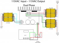
Regarding this, looking at the attached which was taken from your other thread, if I were to wire it in this configuration, would this mean that
1. 90° 115VAC Output will go to the blue wire of the 31813 motor and
2. 0° 115VAC Output will go to the red wire of the 31813 motor
And essentially this would mean I would now need 2 IEC connector (1 carrying the 90° phase and the other carrying the 0°)? Sadly, I only have 1 IEC connector, is there any way to implement this without drilling another hole to my plinth I wonder.
also, a follow up question, how does one determine the optimum results through the phase adjustment? Do i use a stethoscope and adjust the 90° phase for minimal vibration?
Attachments


Hey carlthess40,
I found this website to be a good website to calculate the size of the pulley's Outer diameter that I need
Pulley size and RPM
With regards to the inner diameter, it depends what fit you want, for my motor I went for press fit so I made it 0.002mm smaller than the shaft. (I am intending to use vise bench to fit it) otherwise you can make it slightly bigger 0.001-0.002mm and secure with a grub screw
Hope this helps")
I found this website to be a good website to calculate the size of the pulley's Outer diameter that I need
Pulley size and RPM
With regards to the inner diameter, it depends what fit you want, for my motor I went for press fit so I made it 0.002mm smaller than the shaft. (I am intending to use vise bench to fit it) otherwise you can make it slightly bigger 0.001-0.002mm and secure with a grub screw
Hope this helps
Hey carlthess40,
I found this website to be a good website to calculate the size of the pulley's Outer diameter that I need
Pulley size and RPM
With regards to the inner diameter, it depends what fit you want, for my motor I went for press fit so I made it 0.002mm smaller than the shaft. (I am intending to use vise bench to fit it) otherwise you can make it slightly bigger 0.001-0.002mm and secure with a grub screw
Hope this helps
Yes that’s very helpful. Thank you
Hello,
I’ve recently built two SG-4’s. 1st successfully running twin Premotec Synchro motors in an old Alphason Sonata turntable. Well impressed as the bass got tighter and it became more enjoyable.
Luckily I worked out that U4 was Front to Back 😉
Thanks Bob for the great work!!!
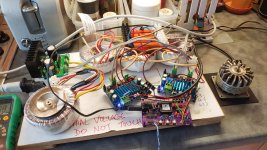
The second SG-4 is for a 3 phase experimental project but something ain't right…
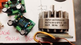
Got me some old Papst KLZ motors.
I ordered some 100 watt 8 Ohm resistors because smaller ones got scorching in minutes.
Rigged up the SG-4: 0, 120, 240 into 3 channels of TPA3116D2 Digital Amp. Running on 12V DC.
Amps into 8 Ohm 100W resistors then into some big 12V to 240V toroidals.
I linked all the blue wires to a star and then the 3 brown wires to a 3 phases of motor.
The motor is running well and measuring about 100V between phases.
BUT the resistors get mad hot in no time. I’m amazed as I thought 100W would be more than enough.
I heard these motors were supposed to be in-efficient but this seems way out.
I can run them easily from a noisy 3 phase industrial control and they run easily single phase with their capacitor.
Have I done something silly?
Being a bit of an amateur I got my meter out to measure current. The AC is pulling over 2 amps when the motor is off. Same current when it is running. The only difference is the resistors get hot.
Help much appreciated.
Waz
I’ve recently built two SG-4’s. 1st successfully running twin Premotec Synchro motors in an old Alphason Sonata turntable. Well impressed as the bass got tighter and it became more enjoyable.
Luckily I worked out that U4 was Front to Back 😉
Thanks Bob for the great work!!!
The second SG-4 is for a 3 phase experimental project but something ain't right…
Got me some old Papst KLZ motors.
I ordered some 100 watt 8 Ohm resistors because smaller ones got scorching in minutes.
Rigged up the SG-4: 0, 120, 240 into 3 channels of TPA3116D2 Digital Amp. Running on 12V DC.
Amps into 8 Ohm 100W resistors then into some big 12V to 240V toroidals.
I linked all the blue wires to a star and then the 3 brown wires to a 3 phases of motor.
The motor is running well and measuring about 100V between phases.
BUT the resistors get mad hot in no time. I’m amazed as I thought 100W would be more than enough.
I heard these motors were supposed to be in-efficient but this seems way out.
I can run them easily from a noisy 3 phase industrial control and they run easily single phase with their capacitor.
Have I done something silly?
Being a bit of an amateur I got my meter out to measure current. The AC is pulling over 2 amps when the motor is off. Same current when it is running. The only difference is the resistors get hot.
Help much appreciated.
Waz
Attachments
The motor is running well and measuring about 100V between phases.
BUT the resistors get mad hot in no time. I’m amazed as I thought 100W would be more than enough.
These resistors are only 100W rated if on a massive heatsink.
Hello,
I’ve recently built two SG-4’s. 1st successfully running twin Premotec Synchro motors in an old Alphason Sonata turntable. Well impressed as the bass got tighter and it became more enjoyable.
Luckily I worked out that U4 was Front to Back 😉
Thanks Bob for the great work!!!
The second SG-4 is for a 3 phase experimental project but something ain't right…
Got me some old Papst KLZ motors.
I ordered some 100 watt 8 Ohm resistors because smaller ones got scorching in minutes.
Rigged up the SG-4: 0, 120, 240 into 3 channels of TPA3116D2 Digital Amp. Running on 12V DC.
Amps into 8 Ohm 100W resistors then into some big 12V to 240V toroidals.
I linked all the blue wires to a star and then the 3 brown wires to a 3 phases of motor.
The motor is running well and measuring about 100V between phases.
BUT the resistors get mad hot in no time. I’m amazed as I thought 100W would be more than enough.
I heard these motors were supposed to be in-efficient but this seems way out.
I can run them easily from a noisy 3 phase industrial control and they run easily single phase with their capacitor.
Have I done something silly?
Being a bit of an amateur I got my meter out to measure current. The AC is pulling over 2 amps when the motor is off. Same current when it is running. The only difference is the resistors get hot.
Help much appreciated.
Waz
I built a similar controller based on work done by @ralpfcooke. It is driving a Papst motor from an Empire table - not sure if it's the KLZ tho. I used different digital amps (TDA7294 I think - would have to check). I needed a small resistor in series with each transformer so the amps saw something other than a inductive load. I used small value, 1 ohm, 3 watt and it works fine. Possibly 100 ohm is too large.
As I read what I've written, I find there may be too man "ifs" to be helpful but I wish you good luck. the information from Ralph is embedded in the following thread:
3 Phase Class D amp for DIY BLDC motor Drive
- Home
- Source & Line
- Analogue Source
- DIY 4 Phase Sinewave Generator for Turntable Motor Drive