I did ask Sota if it would work, they said they were not sure as they have not done any testing with the idler. I am very pleased that I am getting a positive response from the designer, himself.
I am in my late 60’s and am going to enjoy my twilight years playing my analog system....tube amps, etc. I couldn’t undertake the diy as my vision is failing me.
Is there anything I should be aware of to fine tune the drive?
Thank you so much your your assistance.
Kindest regards
Bern2a
I am in my late 60’s and am going to enjoy my twilight years playing my analog system....tube amps, etc. I couldn’t undertake the diy as my vision is failing me.
Is there anything I should be aware of to fine tune the drive?
Thank you so much your your assistance.
Kindest regards
Bern2a
The Condor is user programmable for CW/CCW rotation. I tested the operation with a direct contact idler at 600 RPM and it worked, but I used a cheap O-ring from the hardware store and it wasn't concentric, so I went back to belt drive.
There is a calibration mode to fine tune the frequency of the Condor, and if you have the RR tach, it is moot as the speed will adjust automatically.
There is a calibration mode to fine tune the frequency of the Condor, and if you have the RR tach, it is moot as the speed will adjust automatically.
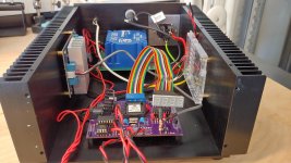
Bill, a few grounding questions. I built a Lenco controller according to your recipe and am building it into a chassis.
- the mounting holes on the SG4 board are grounded. Is the board intended to be at chassis ground or should I use nylon standoffs?
- I've connected the turntable plug ground to the chassis. Does anything else need to be at chassis ground?
- given the PS xformer isolation, doesn't that mean that the SG4 box's chassis grounding (thru the TT 3-wire power cord ground) depends on if/how the turntable is grounded?
I haven't gotten the final panel switches but the noise I was experiencing went away once I connected temporary switches.
I'm also building your tach into the box using a separate 7-segment display. Once I get that working I'll post in the tach thread.
Chassis pic below, note I screwed up the xformer output colors, it is wired correctly.
Attachments
Last edited:
The turntable motor plug ground should definitely be connected to the chassis (earth safety) ground at the power supply. The ground plane on the SG4 can be connected to the chassis ground or isolated; if there is hum in the system, try changing this (ground or unground).
I'm not sure you needed a case with such massive heat sinks; the class D amp will run quite cool and the chassis is not adding any cooling capability from what I can see.
I'm not sure you needed a case with such massive heat sinks; the class D amp will run quite cool and the chassis is not adding any cooling capability from what I can see.
Hi Bill,
Is there a solution to using the Condor on different motors?
I checked with Sota to see if I could also use the condor for other motors as I planned to use it, also on a Lenco L75 and a AA BLWR.
Chris's reply was.....
The BLWR motor has twice as many poles so it runs at half the speed.
It works if your motor flywheel assembly doubles the speed via the flywheel/rim drive.
If you have the BLWR motor I'm assuming you probably assembled the DIY kit (SG4), which would allow that motor to run at 600 RPM.
If you try to run it from the Condor, it will run at 300 RPM.
Let me know how you would like to proceed. We can sell you the condor, just want you to know the possible issues....
Thank you.
My mistake, I didn't realize it was a BLWR series motor. The info from SOTA is correct, it will run at half the speed because it has twice as many poles as the BLWS series that the Condor was designed for.
The Condor will only work correctly with the BLWS motor. It will not work with any motors designed for 115/230VAC.
The Condor will only work correctly with the BLWS motor. It will not work with any motors designed for 115/230VAC.
Thanks Bill.
Yes the chassis is overkill, but it was the right size. And the system runs quite cool to the touch even after a few hours of running. The hottest spot is the SG4 on-board regulator, as I am powering it directly from the 24V supply. I added a heat sink as you suggested but it is hot to the touch.
Thanks again, your designs are so well done and you are always available to answer questions. A real credit to the DIYAudio community!
Hi Pyramid, sorry to be off from the main subject of this thread, but any way... is any suggestion for sufficient quality/price vibration measurement device for small motors and software for it? I know you have vast experience with such kind of gear. It will be nice tool for vibration visibility during SG4 fine tuning. Thank you.
I've used an ADXL-335 accelerometer; it has analog output, 3G full scale and can connect to the mic input of a PC or laptop. I use ARTA software; it's available on-line. ~$79 IIRC.
Thank you.
@Pyramid @Ralfcooke
Hi guys,
Just a quick question on how to wire 2 phase synchro motors.
Is it OK to have the 2 Commons linked on the output of both transformers?
This is linked on my solid state PSU's but I wondered because the transformer outputs are now effectively "floating"...
I have wired it linked due to my old 3 wire connectors and it works fine but I wondered if it would cause interference between the 2 phases?
Should I really use 4 separate wires to the motor?
Best,
Warren
Hi Bill,
Sorry to trouble you again.
Instead of mounting the idler wheel onto the motor shaft to drive the platter directly, would it be possible, if I were to drive the 65mm idler wheel by the circumference of the 6.3mm BLDC motor shaft with the idler driving the platter(similar to the Lenco)?
Are there adjustments to be made on the Condor to enable this to work?
Thank you.
Bern2a
I'm not clear what you are trying to do. If 65mm is the correct size for a pulley to drive the platter at 33 RPM directly on the motor shaft, then it will not work as an idler. The idler wheel does not change the ratio of the driving element-platter, it only transfer torque, so your ratio would go from 65mm-platter diam, to 6.3mm-platter diam.; the motor would have to spin almost 10x faster. The Condor is designed to spin the motor at 600 RPM for 33.3.
Hi,
I'm having a problem with my second SG4 build. The amp seem to go into oscillation and won't settle down. I have tried 3 different 240 to 12v output toroids (20/50/80 VA) and a 240 to 25V with the same problem. I am using a TDK HWS150-24A SMPS to power the TDA7492 amps which should have enough power. I swapped out the TDA7492 for a new one thinking it was the problem.
With no output transformer connected I measure up to 24v AC on the amp output when I adjust the 10k pot on the SG4 output. The signal from the SG4 is also good at around 1.7V AC. I checked the output on a scope when I built it a while ago.
My first build used a cheap ebay SMPS (around 150W) and a 50VA 240 - 2x12V potted toroid. It worked fine from the start. It does oscillate a bit if I adjust the 10k pot but settles down around 200 to 240V. I usually have it at 220v.
Any suggestions appreciated. I did think of swapping the SMPS but I don't want to mess with a working unit.
Thanks,
kffern
Last edited:
- Home
- Source & Line
- Analogue Source
- DIY 4 Phase Sinewave Generator for Turntable Motor Drive