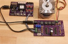
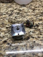
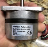
1. ABL-18.432 should be OK.
2. Use MCP101-475DI/TO instead; note this part has a different pin out, but can be rotated to work.
3. You can run 24VDC to the regulator on the SG4 without a step down, but you will need to mount the regulator on a heatsink.
Thank you Bill! Parts are ordered
BTW: I plan to buy 1% metal film resistors instead of carbon. Is it OK?
OK, but not necessary. You could use 0.05% resistors and the precision of the waveform will be unchanged from using 5% parts.
Newly built SG4 pcb - No output, Not oscillating
Hope Pyramid is around to help me with this fault.
Fault:- Newly built PCB. - No output from the SG4 pcb.
LED display OK - shows STBY then 50.00 when Standby pressed.
I have done the following checks suggested by Pyramid in post #787.
1. Reset controller is working. Reset to pin 10 goes high on power up, Is this correct?
2. Crystal is operating at ~18.432 MHz.
3. Make sure the uP is seated correctly
Any help would be much appreciated.
Check that the reset controller is working. The output of U4 (reset) goes to pin 10 of U1 (uP). It should go high briefly at power up then remain low.
If you have a scope or freq counter, check that the crystal is operating at ~18.432 MHz.
Remove the uP from the socket and check that none of the contacts on the socket are bent inward or sideways. Check that all the pins on the uP are straight and uniform. Make sure the uP is seated fully in the socket when you re-insert it.
Hope Pyramid is around to help me with this fault.
Fault:- Newly built PCB. - No output from the SG4 pcb.
LED display OK - shows STBY then 50.00 when Standby pressed.
I have done the following checks suggested by Pyramid in post #787.
1. Reset controller is working. Reset to pin 10 goes high on power up, Is this correct?
2. Crystal is operating at ~18.432 MHz.
3. Make sure the uP is seated correctly
Any help would be much appreciated.
As Ralph said, check the 8v supply to U2 as well as the orientation of U2.
Also check U5 orientation. If everything is installed correctly, look at U5 pin 1 with the SG4 in standby. You should see a 18kHz square wave, 5VPP & 50% duty cycle. You will see the same thing on pins 3, 5 & 9. You should see the same waveforms on pins 2, 4, 6 & 8. If you see the correct waveform on the odd # pins, but not even pins, U5 is bad, wrong part or installed incorrectly. If you don't see the waveform on the odd # pins, remove U5 and check again. If still not there, U1 (uP) is bad.
Also check U5 orientation. If everything is installed correctly, look at U5 pin 1 with the SG4 in standby. You should see a 18kHz square wave, 5VPP & 50% duty cycle. You will see the same thing on pins 3, 5 & 9. You should see the same waveforms on pins 2, 4, 6 & 8. If you see the correct waveform on the odd # pins, but not even pins, U5 is bad, wrong part or installed incorrectly. If you don't see the waveform on the odd # pins, remove U5 and check again. If still not there, U1 (uP) is bad.
Found open circuit between U7 and C12. Bad track or poor soldering , not sure.
easy to link the track, very short link required.
All looked to be going ok 12v now on input to U6, but still no output.
Tested U2 pin 4 = 12vdc !!! should be 8v
Now going to change U6 when I can get one.
Do you think this could have damaged U2 or anything else?
easy to link the track, very short link required.
All looked to be going ok 12v now on input to U6, but still no output.
Tested U2 pin 4 = 12vdc !!! should be 8v
Now going to change U6 when I can get one.
Do you think this could have damaged U2 or anything else?
You have the correct waveform on the even pins of U5? Those pins go to the inputs on U2 which lowpass filters the PWM signal to produce a 50Hz sinewave. What are the DC voltages on the outputs (0, 90, 120 & 240) when the SG4 is in standby?
You have 8VDC on U2 pin4; is U2 pin 11 at ground? 12VDC won't damage the chip; TLC-2274A is rated to 16VDC (single supply).
You have 8VDC on U2 pin4; is U2 pin 11 at ground? 12VDC won't damage the chip; TLC-2274A is rated to 16VDC (single supply).
Could be a problem with the board, check the through-hole plating on the trace next to R18. If it is a track problem then it is rare; did you buy the board from Oshpark, or was it produced elsewhere? I've supplied many from Oshpark and haven't had any problems as yet.
Hi Ralph.
Yes it is a board from Oshpark.
- Home
- Source & Line
- Analogue Source
- DIY 4 Phase Sinewave Generator for Turntable Motor Drive


