Apex BJT STEREO PRE-AMP SB 3.1 2014 - 2020
Hi guys I got this new layout I decide to go back a re-done the BJT pre-amp now that I have more experience I'm gonna posted here please if some one see an error let me know I just make it today I attached the schematic I use on simulation
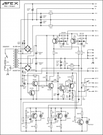
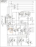
Apex BJT STEREO PRE-AMP SB 3.1
Note: is not tested yet
Hi guys I got this new layout I decide to go back a re-done the BJT pre-amp now that I have more experience I'm gonna posted here please if some one see an error let me know I just make it today I attached the schematic I use on simulation
Apex BJT STEREO PRE-AMP SB 3.1
Note: is not tested yet
Attachments

Might be a noob question: what is the point of the twisted wires? Why not connecting the input signals directly?
I would think that it offers better shielding. Kinda like ur rca wires.
is just a cosmetic decision yes the wire can be just installed directly but it will looks nice in that arrangement the RCA symbol are to solder the wire to a chassis mount RCA'sMight be a noob question: what is the point of the twisted wires? Why not connecting the input signals directly?
Please Confirm for AA11 and AA9
16V-0-16V AC 70VA Transformer is sufficient for two amps (Stereo)...or even less is sufficient since one amp will give max 15W at +/-20V DC
What is amount of bias needed for such an Push-Pull amplifier in Aclass
with steady +/-20VDC PSU @that bias
with output Swing +/-16V_peak @8R0 load
with approcss. 15..16W_average max power
(wrongly, we call this RMS power)?
The output Push-Pull must stay in Aclass operandum even in output Soft klipping situation, so the output (BJT, Mosfets, IGBT, ...)
must be active/ON even then. To do that we must biasing the output stage with 1/2 of the output I_peak current.
Output voltage Swing of +/-16Vpeak @8R0 give us 2Apeak
so we need 1Abias or better some 20% surplus, so 1,2Abias.
This bias at Standby produce 0W output power and 40V*1,2Abias=48W heat dissipation and we get this energy from PSU.
At full output power we deliver 15...16W_avarage power to the load so we got remaining 32W in heat.
We have voltage drop in trafo, in rectifiers, vias...
so we need some 5..10% more power from Mains outlet.
Minimum 110VA 16+16VAC trafo for STEREO AMP will do the job!
Last edited:
What is amount of bias needed for such an Push-Pull amplifier in Aclass
with steady +/-20VDC PSU @that bias
with output Swing +/-16V_peak @8R0 load
with approcss. 15..16W_average max power
(wrongly, we call this RMS power)?
The output Push-Pull must stay in Aclass operandum even in output Soft klipping situation, so the output (BJT, Mosfets, IGBT, ...)
must be active/ON even then. To do that we must biasing the output stage with 1/2 of the output I_peak current.
Output voltage Swing of +/-16Vpeak @8R0 give us 2Apeak
so we need 1Abias or better some 20% surplus, so 1,2Abias.
This bias at Standby produce 0W output power and 40V*1,2Abias=48W heat dissipation and we get this energy from PSU.
At full output power we deliver 15...16W_avarage power to the load so we got remaining 32W in heat.
We have voltage drop in trafo, in rectifiers, vias...
so we need some 5..10% more power from Mains outlet.
Minimum 110VA 16+16VAC trafo for STEREO AMP will do the job!
Thank you so much Mr. Dragon 100
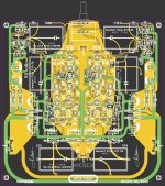
Finally getting time to finish my A38 boards, and noticed something different on the layout. On this one it shows 2 x MJE350 and 2 x MJE340
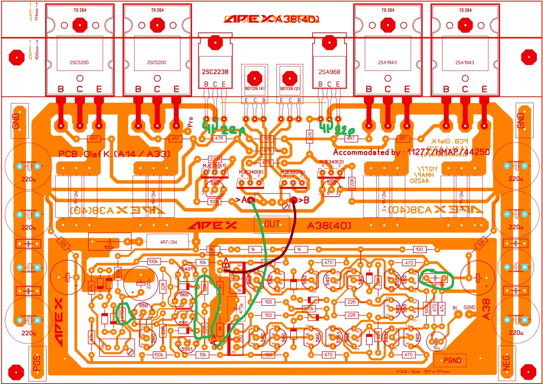
And the layout I used
is this one, which has 3 x MJE340 and 1 x MJE350.
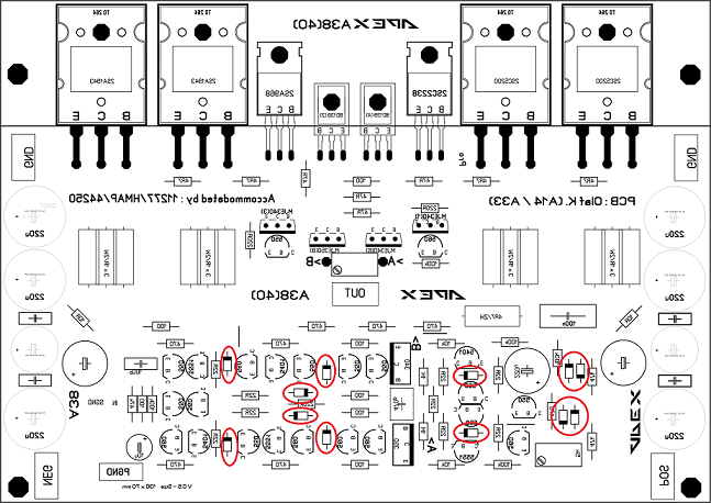
Just want to make sure which one is correct, orange or the white one
And the layout I used
is this one, which has 3 x MJE340 and 1 x MJE350.
Just want to make sure which one is correct, orange or the white one
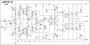
it is always good to have a schematic to compare... 2xMje340 and 2xMje350
I actually found this later last night and fitted 2 x 350's and 2 x 340's. Now that I am finally ready to test, could someone point me to the proper startup procedure for this amplifier, biasing etc. And also, I saw some talk of a bulb tester that is the best option for stopping meltdowns of diy amplifiers. Not sure what it even looks like, would appreciate some help with that as well.
Thanx again for all the help guys
Bulb tester
Use incandescent light bulb only!
The resistor oh the cold filament connected in series with the primary coil of power transformer.
If a short circuit or high Current, due to unnormal cituation is present, you will see a glow lamp and no smoke...
If this occur you need to unplug the socket and try to find what's wrong.
If you see a no glow lamp you can be sure that everything is under control.
In this case you can power your amplifier without using the bulb tester.
Attachments
Last edited:
1. match the i/p transistor hfe to get low offset.Q1-Q2 /T1/T2 OR whatever is named as LTP
2. for bias adjustment trimpot P1(or whatever is the name) is used.
3. Mount the VBE multiplier on one of the o/p transistor with flying wires, if not already sharing the same heatsink as output devices.
4. On first start-up, put a bulb limiter with a 50-60 watt 'incandescent' bulb in series with the mains supply and leave it there for the first couple adjustments. Short your input connection and leave the speaker output open.
5. Bias is adjusted via P1. Keep it nearly in the middle position. apply power through bulb tester and measure the voltage drop across emitter of a pair of output devices(1 NPN and 1 PNP). Bias is given by= emitter del V in mV /0.66 ohm (OR sum of + &- emitter resistance) and current is given in mA (milli Amps). bias current should be around 50-60mA or as per designer's recommendation
6. Measure the DC voltage across speaker out and gnd. It should be less than 30mV, ideally 0-10mV. if there is a pot to control dc offset, use it...
7. observe the bulb at all times. If its lights very brightly, then there is an issue with either a short or bias is too high.switch off everything and keep the pot P1 at zero and switch on again and observe.
8. measure the continuity between collectors of o/p to the heatsink. Then insulation is not proper if there is continuity.
9. If the bulb is not lit or dimly lit, keep turning the pot so that brightness increases slowly. Keep the bias to 50mA to 60mA.
10. If the bulb suddenly lights up very bright from off position while adjusting the bias, then there could be oscillation. Check the zobel resistor R26 for hotness. It should be cool. Hot means amp is oscillating.
11. if everything goes according to plan, then amp is ok and ready for test.
12. Switch off and remove bulb tester. attach a test speaker at output and connect the i/p to a source of music. play at very low volumes, listen for any hum /hiss. A hiss could mean, oscillation or cables are picking up some noise and passing it to the amp.
13.monitor heatsink temperature. , it shouldnt go beyond 50 Deg even at high volumes. Never operate the amplifier without mains slow blow fuse and also quick blow rail fuses. They are the first line of defense against any shorts or faults and will prevent the transformer from melting down.
14. finally, recheck and measure bias and offset again after 30 min or an hour.
Everytime, use the MBT, after changing anything including even moving of wires.
ballistics, make friendship with google, he is very intelligent and he will tell you what you need to know.
YouTube
I would say that you are a beginner, and this amplifier is not recommend for a first, second... amplifier. I wish you good luck!
you should connect incandescent light bulb in series with primary of transformer. light bulb should be 40-60W,not more and not less. trim-pot should be adjusted to half of its resistance measured between middle and both side connections,and then soldiered to its place on pcb.
then connect voltmeter to one of emiter resistor to measure voltage on it. using Ohm's law (I=U/R) calculate current through that resistor-idle current through that one.
have in mind that resistance is in Ohm (0,47 Ohm for example) and voltage is in Volts (0,025V for example,NOT 25mV). so, current is in Amper, voltage in Volt, resistance in Ohm,no mA no mV and no mOhm in calculation.
that all should be measured with heatsink mounted to amplifier transistors. also, input should be short connected.
when you adjust it to say 30mA current through one emiter resistor,than follow what happens with idle current,it can go a bit up or down,that is acceptable in +\- 5mA until amplifier reaches it's working condition. than idle current should be constant. that is a point where you should adjust output offset. that should be measured with voltmeter connect to amplifier output and power ground on PSU. that she be easy to adjust to +\-10mV and also can variate depending on quality of your power supply.
when all is ok,than connect some input signal to amplifier Input,and dummy load at output and measure what happens. do not put too much load on input because now you have load on output and light bulb as narrow throught for current,so with more input signal light bulb will light more. if all is good (offset is ok,idle current does not go (much) higher),than you could connect loudspeaker to output and music signal to input. it is highly recommend to connect some dc-protection to assure loudspeaker. when all is right (offset and idle current) for some longer period of time than is time to remove light bulb and try it.
this is an amplifier with loads of components,and it is very likely that you could have some undesirable soldiered short connections,most likely between pinouts of to92 transistors. be sure to check and double check complete pcb before you connect it to power supply.
I am not trying to scare you,but those are advices given in best attentions. there's even more,wich I can not remember in this moment...
also,have in mind that idle current is the one measured with no any input signal. when you put input signal with load at output,it is natural that current through emiter resistor will increase, depending on input voltage. idle current is measured correctly only with no input signal,or even better with input short connected.
DO NOT MAKE ANY ASSUMPTIONS,if you have any doubts-check and re-check all doubts that could acure. better safe than sorry!
DO NOT MAKE ANY ASSUMPTIONS,if you have any doubts-check and re-check all doubts that could acure. better safe than sorry!
Last edited:
Hi Guys,
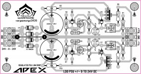
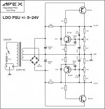
I had an amp short out and burned some parts on my F100 PSU so I designed one with fuses but I'm having trouble getting the relay to engage. Could one of you look over my layout and see if you find any errors?
Thanks, Terry
I had an amp short out and burned some parts on my F100 PSU so I designed one with fuses but I'm having trouble getting the relay to engage. Could one of you look over my layout and see if you find any errors?
Thanks, Terry
Attachments
Hi Guys,
I had an amp short out and burned some parts on my F100 PSU so I designed one with fuses but I'm having trouble getting the relay to engage. Could one of you look over my layout and see if you find any errors?
Thanks, Terry
hi terry this is my circuit i was take from here and there is diodes missing in your circuit. i dont know which one is right. but maybe it can help.
Attachments
- Home
- Amplifiers
- Solid State
- 100W Ultimate Fidelity Amplifier