example:
Iron Pumpkin (which is certainly more critical than Iron Pre, which is having smaller xformers and less wire spidernet) in 3U/280deep Modu case, one Donut (separate secondaries for channels) - 30VA, Static shield, Magnetic shield
no hum, zilch,zero,nada
Iron Pumpkin (which is certainly more critical than Iron Pre, which is having smaller xformers and less wire spidernet) in 3U/280deep Modu case, one Donut (separate secondaries for channels) - 30VA, Static shield, Magnetic shield
no hum, zilch,zero,nada
Attachments

Last edited:
Russ
just a quick peek from my side, not expecting any wire touched in meantime ......
had some quality time with so much Iron, in last 24hrs, or you just did look for tiny hisssesss?

Yes while fiddling with trading preamps around, I decided to check out of curiosity, as Aleph J always been silent as grave. Sure enough I heard as I reported. ear next to drivers couldn't hear from any kind of distance certainly not at listening position.
Fearing it was hokey ground, and wanting to compare I switched BA3 FE back in. Still, same noise. Amp silent with inputs shorted. will be home in hour or so, Fed Ex delivered something I believe is chassis...hopefully.
Near as can tell, pres and amp not cause.
Russellc
Russellc - congrats! Can I borrow your hole mover when you're done with it? Is it the deluxe model with added shrinking attachment too? 
All - I'm working on finishing up my board stuffing for my balanced build. Per usual, I am overthinking things. So, I should be making music soon. I've been agonizing over what pots/attenuation to use. I debated relay-stepped, muse, motorized, dual pots etc.
Until I make a decision, does anyone have a good 4-gang pot they could recommend? I'd prefer not to spend a fortune, but I'd like to use something worthy of this design.
Interested in this also not only for a balanced version, as I am getting closer to BBA3 mono blocks but also single ended. Current unit will use an Alps part from Parts Express. Normally use those Chinese ladder pots.
Only need biggest, most expensive parts for BBA3, transformers and two Deluxe 5 chassis.
Russellc
Only need biggest, most expensive parts for BBA3, transformers and two Deluxe 5 chassis.
Russellc
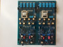
I ordered two of the dual gang pots I used in the SE version just in case I want to try dual pots, and I got a motorized quad gang Alps. I'll be curious to see how pots may or may not have an effect.
A pic of current state is below. For the Iron Pre - I'm waiting on JFETs from the store and my heatsink mounting hardware. The jumpers for In4 and In5 are just temporary reminders. I don't have a timing on the chassis yet, but it seems like they're getting things out very quickly.
For the BA3b => BA2, I'm waiting on some heatsinks to match the output MOSFETs and the JFETs from the store. I've got all the boards built for the monoblocks (minus the components mentioned), but I'm building one stereo non-balanced at first for some listening. Then I'll convert the initial stereo one to the balanced and fire up the other monoblock. I'm anxious to try both output stages.
A pic of current state is below. For the Iron Pre - I'm waiting on JFETs from the store and my heatsink mounting hardware. The jumpers for In4 and In5 are just temporary reminders.
I don't have a timing on the chassis yet, but it seems like they're getting things out very quickly. For the BA3b => BA2, I'm waiting on some heatsinks to match the output MOSFETs and the JFETs from the store. I've got all the boards built for the monoblocks (minus the components mentioned), but I'm building one stereo non-balanced at first for some listening. Then I'll convert the initial stereo one to the balanced and fire up the other monoblock. I'm anxious to try both output stages.
Attachments
I ordered two of the dual gang pots I used in the SE version just in case I want to try dual pots, and I got a motorized quad gang Alps. I'll be curious to see how pots may or may not have an effect.
A pic of current state is below. For the Iron Pre - I'm waiting on JFETs from the store and my heatsink mounting hardware. The jumpers for In4 and In5 are just temporary reminders.
For the BA3b => BA2, I'm waiting on some heatsinks to match the output MOSFETs and the JFETs from the store. I've got all the boards built for the monoblocks (minus the components mentioned), but I'm building one stereo non-balanced at first for some listening. Then I'll convert the initial stereo one to the balanced and fire up the other monoblock. I'm anxious to try both output stages.
If by timing on the chassis you mean DiyAudio store via Italy, mine came in a remarkable short time, despite being given an "unavoidable delay" in Italy.
You should have yours shortly. I'm making layout and beginning to drill holes.
Russellc
Last edited:
I now have Iron Pre in case. All RCA installed. (but only temporarily shorted pair is wired up.) Selector switch not yet wired in, nor is volume pot I intend to start with. Original pots from "Pizza Paddle" board version still hooked up, inside case. I need two extension kits to mount them both.
Question, To wire up the one output pair of RCA jacks to selector switch, how is this done? Looking at my schematic, it appears 2 wires, 1 from #14 on board and 1 wire from #1 on board connect to the center pin on selector switch labeled "C". Then a wire from #4 on board goes to C2....C2 being the confusing part. The C pin is close to 6-11 on back of selector switch, 5-12 on the A half.
My DCG3 pre amp uses the same selector switch, but isn't wired like this, or I cant get it in my head that it is. one of the center pins is connected to a wire labeled ground on the I Select board,(Salas sold by Teabag) then a wire frome each of the relays goes to 1-6.
I don't think this is wired like that, so its confusing me.
To simplify question, I now have pins 2 and 4 jumped on the Iron pre board.
Wires on the #1 input relay are just hard wired to RCA inputs . How do I inject my selector switch in there?
Russellc
I can't be completely certain w/o schematic or knowing your switch... and even if I did, I may not be able to lay it all out but....
You should have 5 inputs and a mute. Figure out which pairs of pins on your board correspond to each input. As an example, I think we determined that for your boards the pair of (1-2) go to Pnegative which is common across all the relays. Either of those in combination with either of the pair of (3-4) activate relay 5.
(1-2) with (3-4) => Input 5
(1-2) with (5-6) => Input 4
.
.
.
(1-2) with (13-14) may be tied to mute ... 13-14 are tied to Ppos on the schematic I reference.
Either way, the mute will be the last one with no relay "click". Note them on a paper. Should be quick. Reference the schematic for certainty, but short pins until you hear the click of the relays.
Note, as mentioned earlier, pins 1-2, 3-4, 5-6 etc. are tied on the PCB (or they should be), so you just need to check one from each of the 7 pairs.
Then, have some fun with your DMM. You can do it faster than I can draw it.
Set it to continuity...
Take your switch and set it to its first of 6 positions... your choice whether you like fully CW or CCW. Take a wire from (1-2) and pick one of the center lugs on your switch. Twist or tack it there. Then, figure out which pin in your switch has continuity to the pin in the center when the switch is in that first position. Usually it's around 1 o'clock if the switch is all the way CCW. Tie that pin to whatever you want it to be ... mute, input 1 through 5. You may want mute in position "1" or "6". I'd recommend twisting (11-12) at the first position at around 1 o'clock, then doing (9-10) at the next position etc., and seeing how that works for you.
You may want to run them in reverse etc. Your choice.
Either way - The rest of the pins will run around the circumference usually from ~1 o'clock to ~5:30. You'll only use "1/2" of the lugs on the switch depending on what switch you got.
Wire it up. Just twist the wires... no solder... Run though all the switch positions. Twist the switch and ensure all relays activate the way you want based on position. Try some tunes in each position... If you like it... solder.
Make sense?
Edited to add - that's how I did mine, but ya never know with me
Last edited:
I now have Iron Pre in case....
bear with me, for always asking same questions - which pcbs you have?
pic is sayin' 1000 words .....
if you want most precise answer, post pics of pcbs and switch you're using
I can reply right now, presuming what you have, but better safe than sorry
in that case, I covered everything more than once......... 
I remember writing and showing IDC pinout, also writing about shorting Lorlin, 2 section, 6 position switch
anyway, will do again, if Russ make an effort to post pictures
though , who need more than one source, nowadays

I remember writing and showing IDC pinout, also writing about shorting Lorlin, 2 section, 6 position switch
anyway, will do again, if Russ make an effort to post pictures
though , who need more than one source, nowadays
in that case, I covered everything more than once.........
I remember writing and showing IDC pinout, also writing about shorting Lorlin, 2 section, 6 position switch
anyway, will do again, if Russ make an effort to post pictures
though , who need more than one source, nowadays
I know, still fighting postage stamp size pics. pulled up paint, just need to play a bit. 2016 boards. Hopefully will post bigger pics tonight. Using Itsallinmyhead's method above I should be able to figure out. Hope prodding around relay area doesn't blow anything up!
Russellc
OK, no need for pics
each pcb IDC must use own switch section, so R channel using one section on switch, L channel using second section on switch
IDC pins 1/2/13/14 (whichever of them) - that goes to common pin on switch
IDC pins 3/4 - pin 2 of switch, enabling input 1
IDC pins 5/6 - pin 3 of switch, enabling input 2
IDC pins 7/8 - pin 4 of switch, enabling input 3
IDC pins 9/10 - pin 5 of switch, enabling input 4
IDC pins 11/12 - pin 6 of switch, enabling input 5
when you look at switch from shaft side and rotate shaft all the way CCW, then common pin is connected to pin 1
one click CW - connected common pin and pin 2
etc.
use buzzer on DMM to check when - on switch
to repeat, last and final iteration of pcbs (which you don't have) - there are flat cables in between channel pcbs and switch ppcb, and there is light show, too
Last edited:
Well, I've gone and done it
Good news first - both channels of the Iron Pre Bal set to 15V00 rails perfectly and 0V000 for all 4 offset checks with no issues.
Now for the not-so-good news.
I am a DODO and don't follow my own advice to check the schematic...and I was excited and hurrying... see where this is going?!
I am reasonably certain that I accidentally shorted RPos and RNeg on what would be my right channel - briefly - while I was checking my potential twister switch wiring. Funny how I was just trying to describe how to do that... Well, at least I got it right on my SE build.
C13 would like to acknowledge the bravery of his close friends ZD1, ZD2, R25, and M3 who gave their lives in the name of human stupidity. ZD2 went out in a glow. Their contributions will be celebrated with a beverage.
After swapping them for fresh new parts, I am no longer failing my dim bulb test spectacularly. However, I have no rail voltage either pos or neg. Something is amiss in the Gemini shunt and/or the relay PSU section. I cannot track it down.
The seers hath peered into the magic smoke and declared that there will be no joy tonight.
I have decided to pause.
Before I make matters worse... I'd appreciate any advice or measurement points to check. Clearly I burnt something else. I have probed but I'd prefer not to use the "good" board as my reference for the moment.
Attached are the schematics I am referencing.
Thanks!!!! Sorry for the dodo move.
More concise version...
1) Checked build after dim bulb and powered up. Rails at +- 15V0 and both offset at 0V000 after minor adjustment. Rock stable.
2) Installed jumpers
3) Prepping for switch wiring. I kept a wire at (+). I moved other shorting wire between 1, 2, 3, 4, 5. I thought I did it properly but I may have hit (-) and shorted Rpos to Rneg. Regardless of the cause ... magic smoke.
4) Checked likely areas and replaced ZD1 and ZD2.
5) Dim bulb check - fail
6) Checked R25 and M3 - dodo
7) Replaced R25 and M3
8) Dim bulb check - pass
9) No voltage at rails. 0V0 (or a brief bit of DC up to ~4V then moves to 0V0)
Last edited:
OK - I now must confess to the world my utter dodoness...
Maybe others will learn. I am proud that I did proper troubleshooting on the other parts. That took enough time.
I am not proud that as I was tracing through the circuit earlier
.
.
.
.
I didn't switch my DMM from AC to DC after checking the transformer.

Well, at least I think it's fixed. I'll get back at it tomorrow. If I can't even set the DMM properly, I need a break.
Rails look good.
You guys are GREAT!
Maybe others will learn. I am proud that I did proper troubleshooting on the other parts. That took enough time.
I am not proud that as I was tracing through the circuit earlier
.
.
.
.
I didn't switch my DMM from AC to DC after checking the transformer.
Well, at least I think it's fixed.
I'll get back at it tomorrow. If I can't even set the DMM properly, I need a break. Rails look good.
You guys are GREAT!
unfortunately, I didn't had space to include fuse on speaker output
Fuses are for sissies!
If I'm gonna be a dodo, I've got to learn the hard way.

- Home
- Amplifiers
- Pass Labs
- What's wrong with the kiss, boy?