We tend to use a BIG 45° bevel on the inside of the circular cutout if we do a double thick baffle...
May be I had a longer day than I thought...
Not certain... no strike that, Im pretty positive I don't understand that response...
dave
Attachments
...many are focusing on stiffening the front panel to improve the good stuff. I think a loud side panel is bad stuff.
My version will probably have 2 side to side braces, as well as the driver/baffle brace. Feedback has been that a well done driver brace impacts midrange DDR.
dave
Just making sure you saw this pathetic plea.
:^)
Dave was talking about connecting the front and back panels. Some prefer to connect all four.
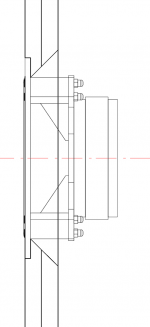
Here is the bracing in a big cabinet. It has a double baffle too.
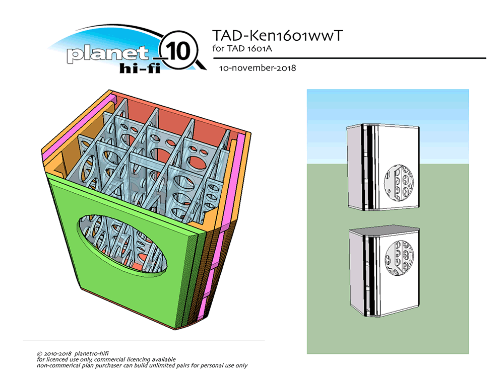
dave
I say modified as I converted the mm to inch (160mm=6.29" and adjusted to 6.25")
Have you actually aquired your material? Often 18mm (at least ply) is called 3/4” in the USA (and here). MDF is pretty consistent, you will find plywood is a “nominal” thickness.
dave
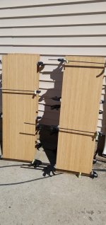
wood arrived at my home, i started to think on how to chamfer routing on driver holes with 35mm thick wall. or just leave it circled?
i also ordered smaller template with 25mm thickness that can be utilized for bookshelf someday
i also ordered smaller template with 25mm thickness that can be utilized for bookshelf someday
Attachments
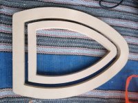
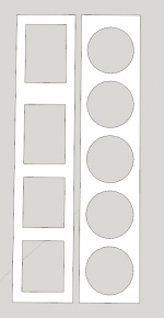
Circle cutouts inherently provide more strength than square cutouts, was thinking about changing the rear main panel as shown...
Anyone care to give me opinions either way ?
There are basically two reasons, the irregular shape it gives to the combined front panel (two pieces) distributes the potential frequencies that it can ring (everything rings, the sound you get from tapping any material is basically ringing) and the other is that the rear of the driver radiation is better into the box and that part of it being irregular also plays a part as the spreads out the frequencies. You could indeed round chamfer it as well, but that is still a single radius that will show up at a single frequency. Like all things nothing is perfect, but the simple technique employed in the Elsinores is quite effective. Keep in mind that the idea that even if only using basic MDF, it would still be a good performance.
Have you actually aquired your material?
dave
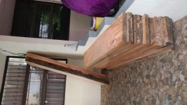
Yes, 1x12 bamboo board, shown is stretched 1x12 (lol) 15.5" wide by 48"
Stretched it by biscuit joiner and tight-bond!
Have 5 panels, 4 are sides and 1 for top's and bottoms.. Doing whats known as waterfall construction. Grain of wood on largest dim's follow up the sides, across the top, back down and under...
The 15" wide panels represent enough movement..
As a highly scientific test, I took two cut offs, that measured almost exactly the same, 1 was 1.080 and the other 1.082...
Put one in a cup of water, nearly 24 hours later it measures 1.090
So, it grew 8 thou when soaking wet. Dont imagine it could get much wetter.
In comparison the second block was placed on a warm surface (Laptop power supply) for almost 24 hours now measures 1.076 or a reduction of 4 thou...
Even if I take the difference, of the two, add them its .012
Since the samples were almost 1" to begin, multiply by 15 and I get a whopping .180 or a hair under 3/16" Since I dont plan on submerging these anytime soon, Id say thats pretty dang stable.
That said, I don't think the planned MDF interior lining will move in those directions. Even if the width changes by 1/2 of the .180 in normal situations or .090, it still could grenade the bamboo so allowances must be figured for movement... Fun times...
")
Attachments
Last edited:
...1x12 bamboo board...
Stretched it by biscuit joiner and tight-bond!
I have a pair that use a similar technique to turn a 50-year old Douglas Fir (a pine) floor into speaker boxes. Here sitting upsidedown on top of a pair (or unnedded) helper woofers.
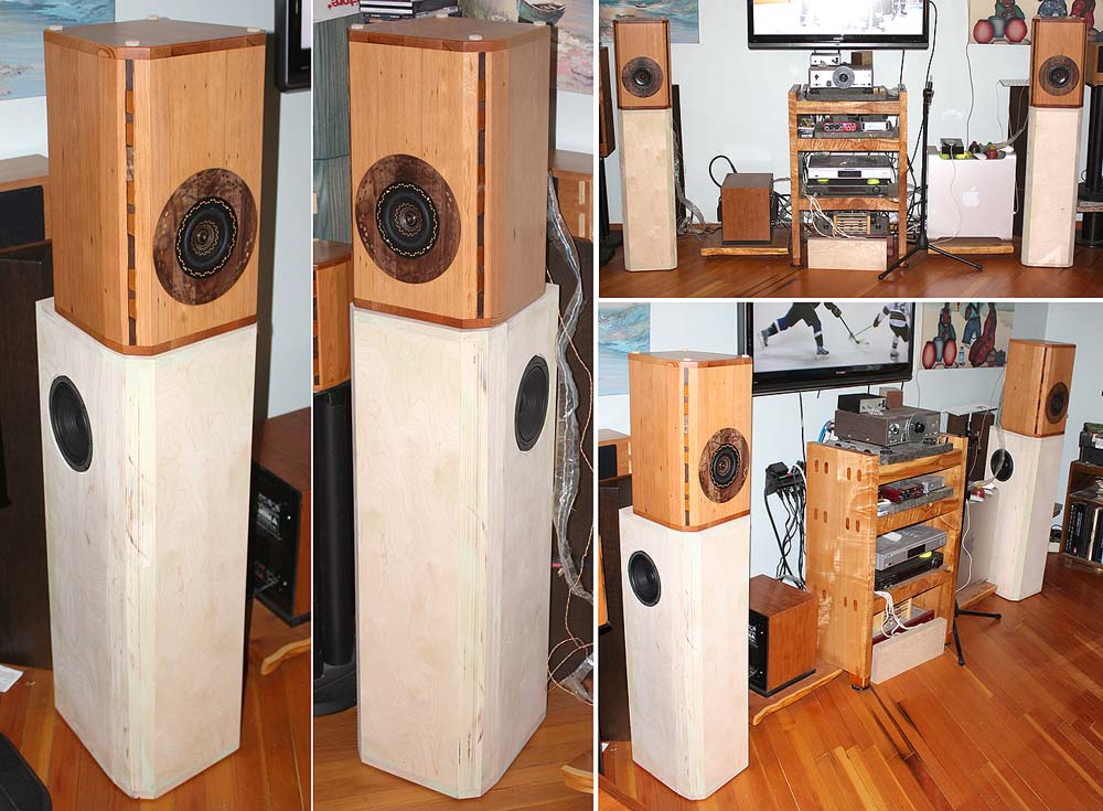
dave
Moisture content and stability is dependent on the wood species and age.
Kiln at 12% is probably a sweet-spot for most Mahogany. Air dry is utterly inconsistent unless it's done in very large humidity controlled environment, and it almost never is.
Also be careful with the type of sealer, some are every bit as unstable (for various reasons) as the wood it's supposed to coat.
It really depends on the kiln drying.Typical commercial kilns dry the timber too quickly and produce timber that is far more likely to be unstable than long term air dried.It is almost cooked and very often over-dried.
I know some smaller millers who use solar or dehumidification kilns and do produce good stable timber but they never rush the process and usually allow the timber to air dry down to about 18% first.
Best of all is timber from logs that have been dead for for many years before milling.You get more waste but the timber seems to completely relaxed and is very stable.They still require air drying after milling however.
So, embarrassingly, sketchup is quite powerful. It allows you to hide everything except the piece or group you want to see. I hid everything an unhid what I THOUGHT was the Main Brace.... Probably haven't seen the real main brace in my drawing for 1.5-2 weeks lol....AFM, I also like a speaker that can sound as good with folk music as it does with metal.
Why do you think of the bridge laying down, are you talking about a horizontal piece with an arch cut into it supporting one line behind the baffle?
Dave was talking about connecting the front and back panels. Some prefer to connect all four.
Anywho, my brainstorm came to me while looking at the the sub front panel and I went to town guesstimating and drawing... lol..
An exercise at least but, one that wont be wasted...
My thought, some what confirmed by Joe, as he called it ringing. I believe is something like resonance. The largest panel again is the side panel. At its edges is bound by parts that run 90 degrees, so should be close to perfectly stiff. This leaves an axis vertically down the center which could flex like the skin on a drum. However small this movement is, will resonate at what ever frequency it likes the most. Its movement will primarily be horizontal.
Since the forces Im trying to controls are moving sideways, the side ways bridge I spoke of, round cutout vs square were to reinforce that side even more.
I had a great theory, but applied it to the wrong dang part!
Now that I have noticed my goofup, understand exactly what dave was getting at, and understand more Joe's response.
Except for trying to reconcile Joe's response with Daves approach and with not loving squares cut in anything that is supposed to be a supporting structure for anything, leaves me simply take in the already refined design with very little to ponder LOLOL
If I would want to tie the two front panels and possibly the tweeter stiffening panel to the (real) main brace, Id have to give it much pondering. I feel like at least in my case, my case will have some expansion and contraction. Allowing for that and creating a super stiff assembly are inherently difficult.
Id possibly use a combination approach. From the vertical center-line behind the front panels, run a spring (not an actual spring) loaded gizmo on a 45 to the point where the main brace was fixed to the side panel... Ideally I need something that can move easily with a little time but be rigid when asked to do something quickly.
(In a highly sarcastic tone...)
Great!, thanks allot... will be on my mind for the rest of the day !

I know that feeling, does Sketchup do layers?Probably haven't seen the real main brace in my drawing for 1.5-2 weeks lol....
I understand this is still being considered, but about the bridge. The brace thickness is distributed properly according to the pressures it will see. This will work due to it going all the way along the wall, however this is not necessarily the best philosophy when the brace connects to a single point along a dimension.This leaves an axis vertically down the center .... the side ways bridge
Attachments

...as he called it ringing. I believe is something like resonance.
ringing = resonance
dave
Except for trying to reconcile Joe's response with Daves approach
re: driver cutouts.
What Joe points out id true. The same reason a square baffle is better than a circular one.
Do keep in mind that in most cases the boxes i design will only use the midBass up to a much lower frequency than in the Elsinore. Down where i typically XO the issue is moot, you just need no restriction on the air coming out of the back of the cone.
So i will pay attention to that when i do my variation.
dave
The brace thickness is distributed properly according to the pressures it will see.
Are you talking about air pressure? That is mostly irrelevant when talking about braces.
dave
I know that feeling, does Sketchup do layers?
I understand this is still being considered, but about the bridge.
Yea, but layers work very differently than one might think. When I first started using it, I wound up drawing half on one layer and half on another.. I wound up calling it bad juju and never looked at layers again.. Been a few years, may be I will see if Im missing out on anything..
Looking at the drawings, and my sketch-up model, I may just be splitting hairs here. Im thinking I need to get along further in the build to see if its worth paying any attention too...
Last time I go near this lol, at least for an entire hour...
The cutout on the left (purty close to Joes org design) has cutouts measuring 1.42 Sq ft.
My idea, shows a total area of 1.36 Sq ft (cut out).
That said, I'd still bet a McDonald's Dinner that my drawing as shown would be stiffer..
But the real question is 2 fold. Would Joe approve (Nothing but respect and love!) and would it amount to anything measurable..
Attachments
re: driver cutouts.
What Joe points out id true. The same reason a square baffle is better than a circular one.
boxes i design will only use the midBass up to a much lower frequency than in the Elsinore. Down where i typically XO the issue is moot, you just need no restriction on the air coming out of the back of the cone.
dave
I know what I know, and this I know, I know nothing about lol.
Never tuned a speaker, never measured anything to do with one...
You fine folks are light years ahead of me with this more tech savy stuff...
Mechanical pressure on the brace, which is probably the result of air pressure.Are you talking about air pressure?
Based on my experience with CAD in general. Copy the whole design and work on the copy (always a good idea). Draw a line nearby (don't modify it after you use it). Select portions a few at a time which you can select on an individual basis only, then displace them along that line. Reselect them and also select more individual portions of the main copy, displacing them all (so the first lot are now double displaced). Eventually you get to the ones you couldn't reach. You can then devise a layer plan.never looked at layers again..
- Home
- Loudspeakers
- Multi-Way
- The "Elsinore Project" Thread