48 bucks isn't bad, good in fact. 40 dollar ship is a bummer. Not horrible, just thinking what could have been!
Such is life,
Russellc
Ok after checking all connections it seemed I didn't have a good contact point on the negative rail I fixed that. I zeroed out P1&P2 and started over I attached two photos to show my hookup for biasing. P1&P2 do work now when I turn them I was able to get 1vdc across R10 & R11 but the DC offset is -17vdc not 0vdc not sure if I have something not hooked upright.
Thanks for the help
Dave


Thanks for the help
Dave
Keep adjusting, one meter shows 100mV, the other 9.8mV
Sorry if I am not getting this. So this is where I am at with 1vdc across R10 the MOSFETs are warming up to 110F

Sorry if I am not getting this. So this is where I am at with 1vdc across R10 the MOSFETs are warming up to 110F
View attachment 821214
Where is the meter connected for DC offset?
Where is the meter connected for DC offset?
From the top of the cap, it's the same if I connect the probe to between R12 & R13 to ground When I adjust P1 up the DC offset goes down but when I bring P2 up the get the voltage across R11 DC offset goes right back up. Because when I bring P1 up the voltage goes up on R10 and the same for P2 voltage on R11 like there reversed Shouldn't P1 adjusting the negative voltage on R11 and the P2 positive voltage across R10
Last edited:
If you go back to zero on P1 P2, do you show zero offset?
I will check and report back thanks
With P1&P2 zeroed DC offset -16.90vdcIf you go back to zero on P1 P2, do you show zero offset?
I could not get to zero P2 brings it right back into the negative and the R10 read 17ohm and R11 22ohmWhile your setting it back to zero, back off P1 first (-V on the meter), see if you can achieve 0V offset, note the voltage readings across R10 & R11. While the meters are hooked up, power off the BA3 and measure R10 & R11's resistance.
So as fo this time I have been working on the Right Channel So I moved to the Left Channel to see if I could bias it. I moved the probes over DC offset from the get-go was Zero as I dialed up P1 & P2 slowly they started to work in tandem with each other like described in post #2 and I was able to get zero offset with 1vdc across R10 & R11 see attached photo. I just need to figure out what's going on with the right channel

Well with further investigation 6L6 was a correct bad solder joint at the ground of the right channel RCA jack those Cardas jacks can be so difficult to get good contact. Once I corrected that at power up the DC offset was zero so I restarted to bias all over and am able to get 1vdc across R10 & R11 and the DC offset at zero. I will get some more photos when I get everything finished up I am excited to get some audio through it. Thanks for helping me out I am sure I have more questions.
Regards
Dave
Regards
Dave

Sure, there are a couple ways. You could use two zener diodes (Figure 1 below) and two resistors. 6L6 was probably posting in a hurry and accidentally omitted the resistors from his description. Or you could use a couple of voltage regulator ICs, one to produce +15V and another to produce -15V (Figure 2 below).
Either will work but I prefer Figure 2 myself.
(BTW Mouser has many many 1N5929B zener diodes in stock. 15V and 3 Watts: link )
_
Anyone know the cap values I should use for the schematic using the regulators?
The datasheets linked in post #1732 include standard capacitor values, right on page 1. I've screengrabbed the relevant portions below.
But diyAudio builders typically worship at the altar named If Some Is Good Then More Is Better.
So diyAudio builders typically install much greater capacitors than the IC manufacturer says is necessary. Builders rhythmically chant More Is Better, More Is Better, More is Better as they install whopping great capacitors.
How much more? Look at the schematics of the Pearl2 phonostage here on this site. Look at the schematics of the H2 generator board here on this site. I think you'll conclude: a lot more. A LOT more.
It wouldn't raise any eyebrows on diyAudio, if someone decided to make Cin = Cout because that means you only purchase one part type ("BOM line item minimization" !) and then use it twice. It also wouldn't raise any eyebrows on diyAudio, if someone chose the capacitance value using this demonic, profligate, diabolical equation
Thus if the maximum current the circuitry can possibly draw under worst-case conditions is 71 milliamps, they would purchase (10 x 71) = 710 microfarad capacitors. Actually, Mouser doesn't sell that value; the next largest E6 standard capacitance value is 820 microfarads. Thus Cin = Cout = 820 microfarads to support a worst case load of 71 milliamps will not raise eyebrows. Or at least, that's what I predict.
Is it necessary? Of course not. It is intentional, deliberate, wretched excess. Which diyAudio just loves.
_
But diyAudio builders typically worship at the altar named If Some Is Good Then More Is Better.
So diyAudio builders typically install much greater capacitors than the IC manufacturer says is necessary. Builders rhythmically chant More Is Better, More Is Better, More is Better as they install whopping great capacitors.
How much more? Look at the schematics of the Pearl2 phonostage here on this site. Look at the schematics of the H2 generator board here on this site. I think you'll conclude: a lot more. A LOT more.
It wouldn't raise any eyebrows on diyAudio, if someone decided to make Cin = Cout because that means you only purchase one part type ("BOM line item minimization" !) and then use it twice. It also wouldn't raise any eyebrows on diyAudio, if someone chose the capacitance value using this demonic, profligate, diabolical equation
Capacitance = 10 microfarads per milliamp
Thus if the maximum current the circuitry can possibly draw under worst-case conditions is 71 milliamps, they would purchase (10 x 71) = 710 microfarad capacitors. Actually, Mouser doesn't sell that value; the next largest E6 standard capacitance value is 820 microfarads. Thus Cin = Cout = 820 microfarads to support a worst case load of 71 milliamps will not raise eyebrows. Or at least, that's what I predict.
Is it necessary? Of course not. It is intentional, deliberate, wretched excess. Which diyAudio just loves.
_
Attachments
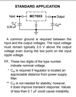
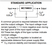
The datasheets linked in post #1732 include standard capacitor values, right on page 1. I've screengrabbed the relevant portions below.
But diyAudio builders typically worship at the altar named If Some Is Good Then More Is Better.
So diyAudio builders typically install much greater capacitors than the IC manufacturer says is necessary. Builders rhythmically chant More Is Better, More Is Better, More is Better as they install whopping great capacitors.
How much more? Look at the schematics of the Pearl2 phonostage here on this site. Look at the schematics of the H2 generator board here on this site. I think you'll conclude: a lot more. A LOT more.
It wouldn't raise any eyebrows on diyAudio, if someone decided to make Cin = Cout because that means you only purchase one part type ("BOM line item minimization" !) and then use it twice. It also wouldn't raise any eyebrows on diyAudio, if someone chose the capacitance value using this demonic, profligate, diabolical equation
Capacitance = 10 microfarads per milliamp
Thus if the maximum current the circuitry can possibly draw under worst-case conditions is 71 milliamps, they would purchase (10 x 71) = 710 microfarad capacitors. Actually, Mouser doesn't sell that value; the next largest E6 standard capacitance value is 820 microfarads. Thus Cin = Cout = 820 microfarads to support a worst case load of 71 milliamps will not raise eyebrows. Or at least, that's what I predict.
Is it necessary? Of course not. It is intentional, deliberate, wretched excess. Which diyAudio just loves.
_
OK, .33uf and 1 UF it is.
- Home
- Amplifiers
- Pass Labs
- The BA-3 as preamp build guide