I have been playing around with the 'double output & double ccs' version of the JLH, not sure about what name that would go under? ESL JLH?
Anyway, what I did was to try the old type current source for the upper output (resistors & capacitor) as in 1969 version, and did some resistor tuning on that to try to get lower distortion (watching distortion spectrum in FFT while tuning). Sadly, there was no significant change compared to using the ccs.
I also tried tuning the '2,2k resistor' at the lower outputs base, but all I could see was that going too low increased distortion, but other than that, distortion stayed abt the same. This was with ccs in place.
Distortion performance is ok, but I was expecting to improve it some more.
For example, 2nd harmonic is abt 80dB below the 1kHz test tone (3rd much lower), and with 13+14kHz, the 1kHz IMD component is around -60dB. With multi-tone input, the 'noise' is abt -80dB at best.
Last edited:
Member
Joined 2009
Paid Member
For example, 2nd harmonic is abt 80dB below the 1kHz test tone (3rd much lower), and with 13+14kHz, the 1kHz IMD component is around -60dB. With multi-tone input, the 'noise' is abt -80dB at best.
this is already very low distortion - before long there will be no flavour left in the pot and you won't know if you are listening to a JLH or not.
I think that 2K2 is to act as ready made Darlintons do. It perhaps makes for a cleaner transistion. It should work without it. One thing I forgot when my version is the current through the driver is due to the output transistor. I was lucky. This was perhaps a good thing because the transistor not getting hot possibly would offer better sound. My Indian 2N3055 have high gain. BC337 will take the current but not the heat. JLH used a chunky device.
this is already very low distortion - before long there will be no flavour left in the pot and you won't know if you are listening to a JLH or not.
I'm only in the learning process, and at the moment the tweaked PNP JLH -69 with floating ground measures best on distortion, and also pleases my ears the most. No other JLH versions (or other amps) have sounded as good to my ears.
Based on this I try to improve the measurements on the other JLH amps.
I have some class AB amps that measure good, but still I don't like the sound as much as the JLH. Based on this, I don't think my measurements tell the whole story, but they seem to give some indication when it comes to differences between JLH amps.
0.1% was considered exemplary for thermionic valve ( tube) based post-war amplifiers.
The open loop voltage gain for the JLH1969 was around 600. With a closed loop gain of 13 the quoted feedback factor is a modest 34 dB.
The circuit is stable without any compensation capacitors as 2N3055 transistors have lower fT than the other transistors and set the dominant pole so the stability margins are adequate.
That is part of the design to exclude out of phase signals getting to the inverting input - it also helps to avoid amplifying noise in the environment. There is more emi about now with rf connectivity conveniences which make life much easier today.
I would imagine IM distortion is the question?
Mainly yes, and this is where my PNP version has the biggest advantage.
When it comes to HF disturbance I totally agree. I wrote about my experience with horrific HF from a plasma TV earlier in this thread, so I definitely think HF filtering is needed.
My brother thought IM distortion was the transistor sound. His ability was to work out the mechanism that were creating it. Alas he died from the flu. I now always have my flu jab. Not just for myself but also so as to protect others.
As said before PNP output transistors often have better gain compared with NPN . This maybe even more so at JLH current settings. Higher current gain should reduce IM distortion. I could imagine 0.7 amps might sound better than 2 amps. I doubt the power output is very different to most people.
As said before PNP output transistors often have better gain compared with NPN . This maybe even more so at JLH current settings. Higher current gain should reduce IM distortion. I could imagine 0.7 amps might sound better than 2 amps. I doubt the power output is very different to most people.
On my PNP, the best measurements were around 1A Iq.
I tried some simulations on the dual rail, dual ccs version to see what I could do for hum reduction.
It seems that 100Hz hum can be reduced abt 25dB by adding 10Ohm and 10mF to the positive supply rail for the ccs:es. That is 10ohm in series, and a 10mF to GND. This is the best I have found so far. Connecting the capacitor to negative rail makes it worse, and trying a similar filter on the negative side also makes it worse. Just to clarify, the outputs are not filtered, only the low current part.
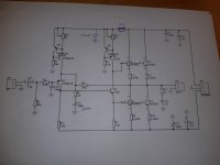
With your continuing variations Rallyfinnen, I can't follow your descriptions - only guess. How about a clear schematic or at least a sketch of the schematic that is current now, so that we can see what you are actually up to now, what you are proposing and what you have already scrapped and removed. It seems that your basic design is or was a reverse-polarity JLH96 design.
It's a bit off-topic for the thread but it's always interesting to revisit the general design issues through other people's perception of audio electronics and electronic theory.
It's a bit off-topic for the thread but it's always interesting to revisit the general design issues through other people's perception of audio electronics and electronic theory.
Sorry. I know it can get confusing with a long thread like this, and several discussions going on. Especially since I have several versions of the amp too ")
So far there is only simulations, no modifications done. See the attached picture of what I have found so far.
When I compare the ripple voltage in my simulation, it goes from abt 28mVpp to 2mVpp when I add the RC.
I also tried filtering only the ccs for the input transistor by moving the RC 'one step to the left', but that did not do much.
Just now, I also simulated the start of a 20Hz sine, and it seems the feedback cap to GND has some impact on the transient behavior here. With the standard 220u it takes a few cycles to get the full amplitude, but it's a lot better with 1000u, so I marked that one for modification too. I think there is some more simulation to do here, I also see some settling time when the sine stops abruptly.
Seems there is a small DC-offset created, so the first positive peak of the sine is lower, and the following negative is also lower. So there is a small DC offset in the beginning when the sine input starts. How it affects the 'punch' in the sound I have no clue..
Some input from people with more simulation experience would be welcome
Attachments
Last edited:
Member
Joined 2009
Paid Member
The phase splitter, Q3, current source is not decoupled - that's another improvement. You can try a cap to ground from the base of Q8 but the usual way is to split R8 into to two resistors and take a cap from their junction. It is sometimes better if that cap goes to the +Ve rail instead of ground depending on whether a source or sink.
Ah, like this, except for the second ccs:
(from here: The Class-A Amplifier Site - JLH Class-A Update)
The PCB actually has the option for this on the ccs for the input stage. I did not populate that since I read about the oscillation problems with it. But if I simulate it, it should give an indication on how much difference it makes, and if it's worth the extra effort. The RC is a relatively easy addition.
The current setting depends on your power supply type, the expected supply voltage and your speaker impedance and output power requirement, available heatsinks etc. Take a look at the original magazine article and specifically at tables 1 & 3. The link is to the Class A site hosted by ESP (Rod Elliott) and covers many later variations and other designs too. https://sound-au.com/tcaas/jlh1969.pdfDuffo adele;6075378...what power for the transformer how much you set the quiescent current thank you
So, you likely need to consider your limitations, how hot the amplifier and everything inside and around it may become and what you want to do with the amplifier etc. before choosing your power supply options.
Last edited:
It's been too many years for me to offer useful advice in your simulation, beyond suggesting a period of calm for the model to settle before you whack it with a signal.Seems there is a small DC-offset created, so the first positive peak of the sine is lower, and the following negative is also lower. So there is a small DC offset in the beginning when the sine input starts. How it affects the 'punch' in the sound I have no clue..
Some input from people with more simulation experience would be welcome
Back in the real world, clipping events can cause DC offsets which (particularly as you bump capacitor sizes up) can take a long time to return to normal bias conditions. It's a common failing in high-loop-gain/high-feedback amps.
thoglette: I did let it settle before about 3s before starting the sine. It seems to be pretty stable at that point. I have not simulated clipping more than by mistake..
Loudthud: I'm not sure I understand the question? I have not simulated the Zero zone PNP at all.. I only modified it to floating ground, and adjusted some resistor values in the current source to reduce distortion, and added some HF filters (RC)
I posted the schematic for it somewhere in this thread.
I've been looking for bipolar electrolytics in the +1mF range for the feedback cap, but I have not found any good candidates in stock in Sweden or Europe. A lot in the US though.. but shipping from outside EU makes it expensive. They need to be pretty small to fit the PCB etc.
Suggestions welcome.
Build up a shopping list that allows you to buy through Digi-Key's Swedish agency without any delivery charges at all. It doesn't take long to do that with capacitor purchases and they are pretty fast too....I have not found any good candidates in stock in Sweden or Europe. A lot in the US though.. but shipping from outside EU makes it expensive. They need to be pretty small to fit the PCB etc.
Suggestions welcome.....
- Home
- Amplifiers
- Solid State
- JLH 10 Watt class A amplifier