I can buy one today. Is there any suggested value for heatsink and mosfets?
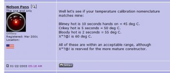
Nelson says 20C above room temperature max. The commercial F5 runs at 25c above which is where mine is when biased at .7v. He also says you should be able to keep your hand on the sink for 5 seconds.
Measuring the MOSFET bodies helps to determine if heat is being effectively transferred to the sink.
Here's a helpful guideline...
Great explanation thx. Mr.Nelson.
If you decided to couple f5 with preamp which one is your choice.
B1,
B1 R2,
B1 with KORG Triode,
Mezmerize B1
Ba-3
Regards...
Last edited:
Potstip is very clever IMHO. He accumulated lots of parts and PC boards while working and now that he has cleverly and correctly quit his job, he has time to assemble amps! Which helps lower stress due to having no job...I think Zen Mod would approve.... ")
You need a part time job to buy all those Z-foil resistors!
Last edited:

11 years??? Say it ain't so... I remember prowling the magazine racks waiting for the AudioXpress copies to drop .
I just biased this p2p build today. I should have the second channel put together this evening. Hopefully getting it cased up will take significantly less than 11 years. I'm stoked despite the delay. Thank you Nelson. I have the parts necessary for a f5t, f6 and m2 around here. Decisions, decisions.
Darren
. I just biased this p2p build today. I should have the second channel put together this evening. Hopefully getting it cased up will take significantly less than 11 years. I'm stoked despite the delay. Thank you Nelson. I have the parts necessary for a f5t, f6 and m2 around here. Decisions, decisions.
Darren
Attachments
Hey 6L6, do you maybe recognize the heat sink pictured? I believe I bought that from you 5 years or so ago.
So, M2 huh? I'll have to go back and do a bit of reading. The one order I'll have to make is the little lm385s. At least they're cheap.
Shy of a few PS caps and heat sinks for a couple amps, I think I have everything else to build them all.
Come to think of it, a buddy of mine was building something for the Navy with BIG chunky aluminum pieces. I think an off cut scavenging visit is in order...
Darren
Noob question... I am using an Antek AS-4218 for the PS and the DIY store PS board. The Xformer has a red and a black wire for each primary and a blue and green wire for each secondary. How can I tell which set of wires are associated on the same coil? I know using a VOM and putting DC on a transformer can cause a nasty spark. Any other way to do this or am I wrong about a problem with a continuity test on an Xformer? http://www.antekinc.com/content/AS-4218.pdf
11 Years Thank You Mr Pass, I should have brought shares in a electricity company all those years ago but no regrets just appreciation, I could never have afforded to buy a commercial one this good, Thanks to all contributors as well for making this whole DIY a success for all.
But I now have a problem advise please.
On some of my music I've stopped playing as its got to grainy (maybe no wright expression) Some voices nice, others irritate, I suspect its all part of the ageing process, (Tinnitus)I thought of changing to a F6 build, as it simple like F5, also was referred to as a "old mans amp" on 6moons, My speakers are 6ohm and I prefer to use Headphone output on my dac,(cord mojo) as input on F5,
any thoughts please?
I thought of changing to a F6 build, as it simple like F5, also was referred to as a "old mans amp" on 6moons...
Yes, I always trot out the F6 when listening to Montovani or Lawrence Welk.

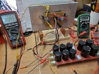
I am considering the fins-to-fins scenario, for a certain amplifier. As the heat-sinks are actually made of metal, with electrical screening capability, I was wondering if it would be feasible to insert the following between the fins: Toroid transformer, 4,5 cm height, sideways; Rectifier board and main rectifier caps: 4,5 cm; PCB with ripple eater, module height 4,0 cm.I verified my conjecture about the chimney effect of the heatsinks mounted fin-to-fin in my F4 amplifier. Each channel is biased to 1.36A with 22.6V rails for a total of about 125W total dissipation. I measured ambient and heatsink temperatures for two configurations: fin-to-fin and fins outward as shown in the photos. The temperatures shown were after more than one hour and were stable.
fin-to-fin fins-outward
ambient: 20.1C 20.1C
left channel: 42.3C 44.9C
right channel: 42.3C 44.9C
<sorry - I cannot figure out how to present a table with this "editor">
Basically, all these noise producing elements would be between the metal fins (fin-to-fin), within the central section. In hope of the screening effect as promised by the two heat sinks.
But my question is the following: If this "chimney" is now 4,5 cm wider, it has a bigger cross section. Will such increased cross section of the chimney diminish the effectiveness of the chimney?
My heatsings are 30 cm long and 19 cm wide, with fins 5 cm heigh.
If I arrange this vertically, I will get a 30 cm high chimney, 19 cm deep.
The "space" or "width of the chimney would now constitute of 5 cm inter-fin-area; 5 cm sideways oriented components area; 5 cm of inter-fin area.
Will the convection in such chimney be comparable to the one presented above?
- Home
- Amplifiers
- Pass Labs
- F5 power amplifier