summer summary
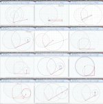
Here some simulations of known geometries, made with Linkage program (thanks to Jcarr that gave us this precious link, and to Dave, the author)
Download Linkage | Dave's Blog
Surely can be further optimized, and many others are around to be investigated; Even better to do them in a program able to do a vectors breakdown too.
Hope this can be useful, or amusing
carlo
Attachments
This is what it looks like.
YouTube
The only constraints are main jewel pivot and the cams.
There is no tangency errors anywhere.
Not shown is anti-skate/anti drag force mechanism that is still needed.
All the frictions are simulated along with gravity and with a 0.0009N force vector along the tonearm tube it rotates the arm across the play area in about 140 seconds.
The 2 counterweights are not modelled.
I was looking for software to design the cams but could not find anything so I had to write the function in excel and use that data to model.
The math works out perfectly to 11 decimal points for both cams but as can be seen in the last pic there is some cam slip, but only 0.5 micron for the last quarter of travel. I suspect this might be an rounding error somewhere.
The noise in the plots are from hitting cam constraints.
To manufacture is turning out pricey because it has to be wireEDM cut from the high tolerances.
Won't be built at this time.
Hello 2wice,
Wire EDM is not the way to make those cams. they should be CNC machined.
EDM leaves tiny pits on the surface of metals causing the cams to interlock with each other.
What keeps the center cam in contact with the tone arm cam?
Can the cams loose timing with each other?
Is the semi circular arc with the three black dots at the left a ball bearing?
Sincerely,
Ralf
Hello 2wice,
Wire EDM is not the way to make those cams. they should be CNC machined.
EDM leaves tiny pits on the surface of metals causing the cams to interlock with each other.
What keeps the center cam in contact with the tone arm cam?
Can the cams loose timing with each other?
Is the semi circular arc with the three black dots at the left a ball bearing?
Sincerely,
Ralf
Hi Ralf
I cannot find anyone willing to CNC the cams for me with 10 micron precision.
WireEDM can go down to 5 micron.
It needs to be that precise because the cams have a 50 micron gap between them.
There is a rolling surface between the cams that keeps the cams from slipping.
That rolling surface is not modelled as I'm getting IP on that and the drag force counter.
Won't work without those.
That is not a bearing it is another cam.
Cheers
Trenton
Hello 2wice,
5 micrometers equals .0002". I operated a Haas CNC machine, when I took one semester of CNC machining and programming at a local community college two years ago. That machine was able to hold that kind of tolerance.
The drag force and the resulting skating force are difficult to control, because they change constantly.
Sincerely,
Ralf
<<10 microns ....
Hi 2wice, this belongs more to grinding & lapping than to machining, computerized or not. Sure you need that kind of tolerances in a rolamite like device?
At first sight i'm more worried of cames and their shape, especially in the second half of travel: cames were born to work against levers, or pistons, than against each other. (tags: Camalot - "Friends" - climbing.... that remembers my youth)
carlo
Really a great work, i'll love to see it in action
That machine was able to hold that kind of tolerance.
The drag force and the resulting skating force are difficult to control, because they change constantly.
Hi Ralf
I should have clarified, can't find anyone here to machine a 1 of at the tolerance.
They want to charge the same rate for 100 units. Some of the parts are only 4mm wide.
EDM they can do that but still pricey.
I've designed a non contact constant torque mechanism at a fixed value, it's in a cartridge format so if you prefer another value it can be changed out instantly.
Hi Carlo<<10 microns ....
Sure you need that kind of tolerances in a rolamite like device?
At first sight i'm more worried of cames and their shape, especially in the second half of travel: cames were born to work against levers, or pistons, than against each other.
Yes that tolerance is required, they can bind if it's too far out.
I can't find examples of cams used in this way, they work fine in simulation.
Only worry is the increased velocity in the last 3rd of travel, but I'm hoping to counter it by targeting that area with the counter torque mechanism.
Just saying that two counter-rotating cams look like a perfect self-locking mechanism, generating increasing side loads on shafts (climbers entrust their life on it); But the rolamite ribbon can probably change everything, because the loads are no longer radial. no experience about this
Carlo
a mock up before making expensive parts?
Carlo
a mock up before making expensive parts?
A little late, but it lasted a while to read the whole thread.
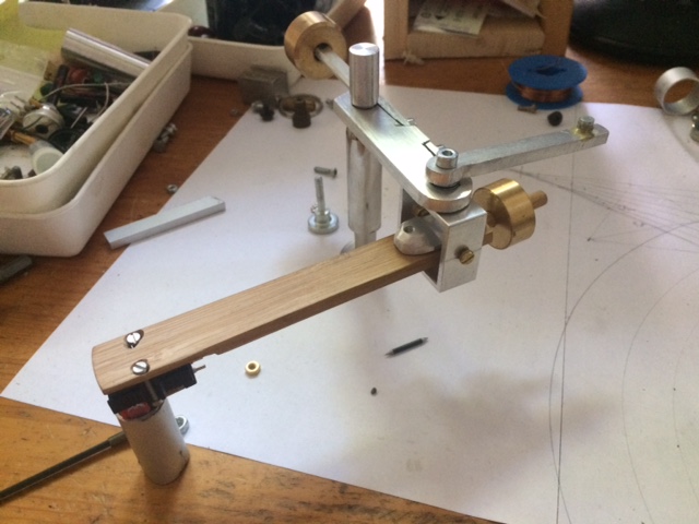
I think i have a practical solution for something between The Schröder LT and the other suggestions:

The Construction is very simple, done by a ruler an other piece of paper and a compass.
I added a counter weigth against scating, its force depands on the angle in witch the main pivotarm is moving.
The second pivotarm will be made by a small wire or nail of steel. At the end of the pivot wand is a little neodym magnet fixed, this will damp the arm movings and will lead the wand in a specific curve, the profile can be seen on the drawing as points in the top left edge.
the horizontal armbearing will be made with tiny jewels fixed in a hole at the end of an M-3 brass-Screw.
Uwe
I think i have a practical solution for something between The Schröder LT and the other suggestions:
The Construction is very simple, done by a ruler an other piece of paper and a compass.
I added a counter weigth against scating, its force depands on the angle in witch the main pivotarm is moving.
The second pivotarm will be made by a small wire or nail of steel. At the end of the pivot wand is a little neodym magnet fixed, this will damp the arm movings and will lead the wand in a specific curve, the profile can be seen on the drawing as points in the top left edge.
the horizontal armbearing will be made with tiny jewels fixed in a hole at the end of an M-3 brass-Screw.
Uwe
Attachments
Yes, thanks dtut for the warm welcome.
It's a little disconcerting finding a theme that moves your brain for years and getting brain grease by reading post by post. Thoughts you have build a similar opinion upon and some you haven't just sensed. My be I can add a little input by my contribution.
For me it began in the 80th when I got some money it was clear, the first thing that I'll have to get was my own Hifi equipment. At this time I bought me a PS-LX55 Linear Tracker
 to get a sophisticated solution for playing my LP's. But it was to disappointe me. I had a KEF TML builded and the motordriven movement of the wand led to supersonic bass artefacts. In normal setups you may not notice them, but my amp and TML made it possible. My conclusion is by now: motordriven wands have to move continously, correction has to be made by variation of speed, not by on/off. You have to avoid the interim of sticking and gliding in the linear bearing.
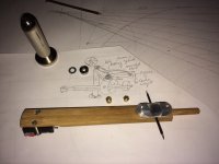
Last Winter I builded a passive tracker by using a linear ball bearing like this.

the remains are the shown bamboo wand and the frame:
But friction in the bearing did concern me and I quitted when it was finished.
Yesterday I went in the building supplies market and got me some aluminium profiles. Then I begun...
This morning the glue is dried, I have to make the iron bow (nail) one again because the fixation was not strong enough. Lazy me, I didn't use oil by cutting the thread.
Uwe
It's a little disconcerting finding a theme that moves your brain for years and getting brain grease by reading post by post. Thoughts you have build a similar opinion upon and some you haven't just sensed. My be I can add a little input by my contribution.
For me it began in the 80th when I got some money it was clear, the first thing that I'll have to get was my own Hifi equipment. At this time I bought me a PS-LX55 Linear Tracker
Last Winter I builded a passive tracker by using a linear ball bearing like this.
the remains are the shown bamboo wand and the frame:
But friction in the bearing did concern me and I quitted when it was finished.
Yesterday I went in the building supplies market and got me some aluminium profiles. Then I begun...
This morning the glue is dried, I have to make the iron bow (nail) one again because the fixation was not strong enough. Lazy me, I didn't use oil by cutting the thread.
Uwe
Attachments


OK, maybe that's it
I had to transcode the video to get a playable format, but foregive me please, now its lying on the side, don't know how to get it upright.
I think by moving by hand its working. Now I have to implement it on my Turntable and check scating. I have already adjusted the needle to 1.5 gramms. forgive me not to use a super duper Needle but I think MCs are little bit over the top, can' t change the tip.
cheers Uwe
Attachments
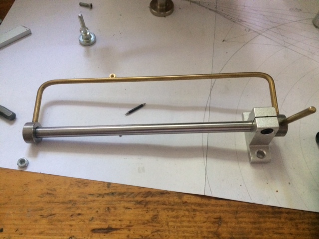
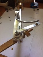
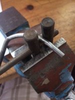
In addition I want to show ohw to bend the bow:
It will last a while until the curve is exactly like on the plan but Its dimensions are not so tiny like on the LT.
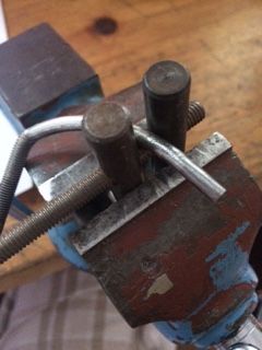
In this manner it is more DIY-friendly you don't need High tech equipment. By hand you can get astonishing precise results and you do it only one, so time does not matter really.
I didn't really need my Lathe, but it does help. Manly you need a jigsaw handdrill, some thread cutters a vice and a pair of good files and a good oil.
It will last a while until the curve is exactly like on the plan but Its dimensions are not so tiny like on the LT.
In this manner it is more DIY-friendly you don't need High tech equipment. By hand you can get astonishing precise results and you do it only one, so time does not matter really.
I didn't really need my Lathe, but it does help. Manly you need a jigsaw handdrill, some thread cutters a vice and a pair of good files and a good oil.
Attachments
My conclusion is by now: motordriven wands have to move continously, correction has to be made by variation of speed, not by on/off. You have to avoid the interim of sticking and gliding in the linear bearing.
Uwe
Uwe, you have hit the nail squarely on the head! However, the on/off action seen with many servo-driven linear trackers is not a problem intrinsic to servo technology. When present, it is due to the design of the servo loop in the particular turntable. I have modified a Rabco SL8E with an opto-electronic servo control circuit that does indeed operate in a continuous, variable speed mode. IME your conclusion is correct - that is the right way to do it. But, this is getting off-topic. I don't want to hijack the thread so, for those interested, here is a link to my work: https://www.lencoheaven.net/forum/index.php?topic=18696.msg279435#msg279435
Your use of the magnetic guide is interesting. In your video the magnetic coupling action seems a bit loose. There is some fore/aft movement along the groove when you swivel the arm back at the "end of the record", likely due to the rubber-band effect of the air gap between the magnet and the guide rod. Changes in stylus drag which come with varying groove modulation levels could pull the arm along the groove and result in audible pitch instability when playing an actual record. Frank Schroeder uses very small air gaps in his arm designs.
Ray K
Hello diyrak, many thanks for your answer.
Yes you're rigth, there is a swiveling in the magnetic coupling between magnet and the leding bow, but please notice that the system is adjusted to 1.5 grams and just by grinding over the paper the arm holds the coupling and don't leave the track. The idea is to give forces the chance to get in an equilibrium by self justage, this coudn't be
done with strict coupling. I think the LT will behave similar on likely conditions, maybe someone who ones one can proof this.
A smaller air gap would have reqire more precision and I choose to make the arm DIY-friendly, most of us have not access to a water beam cutter.
Thanks for the link, this is exactly what I thougt might have to been done. Unlike in the 80th, in nowerdays you have access to microcontrollers and with an ardurino plus motorshield it is going to be possible to solve the problem.
Uwe
- Home
- Source & Line
- Analogue Source
- Angling for 90° - tangential pivot tonearms