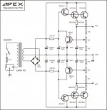
FX100 PSU
Is my question so foolish that no one wants to answer.
Can anyone guide with Fx100 Psu. I have 24-0-24 psu and 30-0-30 transformer. Is there any specific formula to calculate parts value.
Kindly answer. I have not been able to power up my amp because of psu.
Is my question so foolish that no one wants to answer.
Is my question so foolish that no one wants to answer.
Maybe this could help: Sursa alimentare + protectii amplificator Apex FX100 PSU - Accesorii audio - ELFORUM - Forumul Electronistilor
(use Chrome with auto translating).
Maybe this could help: Sursa alimentare + protectii amplificator Apex FX100 PSU - Accesorii audio - ELFORUM - Forumul Electronistilor
(use Chrome with auto translating).
Sorry Sir. Could not understand anything. Only if some one could point out the formula for different voltages so I dont have to ask every time.
Sorry Sir. Could not understand anything. Only if some one could point out the formula for different voltages so I dont have to ask every time.
Are you asking about how to find the DC voltage after rectification?
If that's the case, then it's easy. You take the AC voltage and multiply it with 1.41.
So your 24VAC transformer will give you around (24*1.41)= 33.8VDC, and your 30VAC transformer will give you around (30*1.41)= 42,3VDC.
Please remember that the voltage is not stabilized, it can and will vary depending on your input voltage from your mains sypply. And it will also be higher, when there's no load on the transformer.
So remember to add enough safety margin on your capacitors voltage limit. To be safe you might want to chose 50V caps for the 33.8VDC, and 63V caps for the 42.3VDC.
Sir, I am trying to understand the changes i need to make on FX100 psu + protect to make it work on above mentioned voltages or any voltage from 24 0 24 to 42 0 42.
Sir, I am trying to understand the changes i need to make on FX100 psu + protect to make it work on above mentioned voltages or any voltage from 24 0 24 to 42 0 42.
Hi viki_v2
PSU Fx 100 does not provide adjustable feed voltage.
You can use PSU 10 for 30 V ac, but replaces Zenner 24v with 6V to have 24V to 42 V dc. The thread is big and I haven't PCB.
Attachments
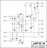
Otherwise the schematic follows the original AX-14. I am collecting the parts to build it.
Hi Prasi,
Wonder if you had a BoM available for your boards? I am starting to gather parts for another build..

Hi Prasi,
Wonder if you had a BoM available for your boards? I am starting to gather parts for another build..
Hello Avtech,
Here it is attached. I didnt have it, but I just prepared it in one go as a guideline for you. Please be careful in using it.
I havent included any part nos for 1/4W MFRs. I think those would be available in your parts bin.
If you find any corrections please post back here again for others.
regards
Prasi
Attachments


I have it shared here. You may download gerbers.
W61084ASN13_apex ax14_total new_2pairs_rev1- Share Project - PCBWay
let me know if its not convenient, I can post here as well.
regards
Prasi
Hi Prasi,
Could you please let me know whether this board is tested or not. I would like to get the boards done from pcbway.com.
Also, I remember like somewhere in the thread it is mentioned like the bias transistor BD139 should be on the same heatsink where the power transistors are installed. Is that important for AX14?
Thank you for the support
Sha
Hello Sha,
I dont know if its tested or not. I am in the process of gathering parts for the build it (for quite some time now).
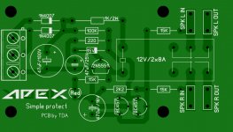
yes the bias transistor has to be on the main heatsink or on the o/p device.
If you see the mage of silk, it mentions to put the BD139 on the o/p device.
regards
Prasi
Edit: One member has built it, and it went up in smoke while doing some measurements , short somewhere I am guessing. He is building another channel.
I dont know if its tested or not. I am in the process of gathering parts for the build it (for quite some time now).
yes the bias transistor has to be on the main heatsink or on the o/p device.
If you see the mage of silk, it mentions to put the BD139 on the o/p device.
regards
Prasi
Edit: One member has built it, and it went up in smoke while doing some measurements , short somewhere I am guessing. He is building another channel.
Last edited:
Hello Sha,
I dont know if its tested or not. I am in the process of gathering parts for the build it (for quite some time now).
yes the bias transistor has to be on the main heatsink or on the o/p device.
If you see the mage of silk, it mentions to put the BD139 on the o/p device.
regards
Prasi
Edit: One member has built it, and it went up in smoke while doing some measurements , short somewhere I am guessing. He is building another channel.
I'm the one who blew it but I don't think something wrong with the board. I have check the schematic with the board layout, I find nothing wrong.
It went into smoke because I short the circuit some where while trying to measure something on the board. The board is crowded so you must be careful when doing a measurement.
Now I'm in the process of building another one, I'll let you know.
Hello Sha,
I dont know if its tested or not. I am in the process of gathering parts for the build it (for quite some time now).
yes the bias transistor has to be on the main heatsink or on the o/p device.
If you see the mage of silk, it mentions to put the BD139 on the o/p device.
regards
Prasi
Edit: One member has built it, and it went up in smoke while doing some measurements , short somewhere I am guessing. He is building another channel.
Thank you Prasi for the update. I missed the note regarding bias transistor placement which you have kept. Will take care of that while populating.
Thank you
Sha
I'm the one who blew it but I don't think something wrong with the board. I have check the schematic with the board layout, I find nothing wrong.
It went into smoke because I short the circuit some where while trying to measure something on the board. The board is crowded so you must be careful when doing a measurement.
Now I'm in the process of building another one, I'll let you know.
Thank you Chat72. Please let me know once you are done with your second board
. I ll put the PCB order on hold for now.Thank you
Sha
Mr Shabusf,
From which shop you source these components in India?
Hi Katiyar,
None of the items are from offline shops. Most of the items are from an Aliexpress seller who sells genuine parts . And some are from taydaelectronics.
Thank you
Sha
Thanks. Please name the seller and how do you make payment?
Hi Katiyar,
Please check the below link, you may not find all the values here. I made payment through my hdfc card.
Hi-Fi Capacitors - Shop Cheap Hi-Fi Capacitors from China Hi-Fi Capacitors Suppliers at ATOPELEC Store on Aliexpress.com
Regards
Sha
Last edited:
- Home
- Amplifiers
- Solid State
- 100W Ultimate Fidelity Amplifier