Seems most here don't understand power supply rejection ratio. It is not a single number no matter how often just one number is quoted. The second often ignored parameter is frequency. The assumption that as long as it is respectable at audio frequencies ain't really right. Higher frequencies can shift the operating point of bits of circuitry.
Then there is the issue of how stray electromagnetic interference gets into the circuit. Easy to understand the electro part. As soon as the EMI enters the chassis it can couple to not just internal wiring but into the case and even into the ground plane.
Thus even if you could get PSSR of 100 dB + the interference would still be much greater in the final product.
Yes I do use a buzzer box to create AC power line noise. I also use an audio power amplifier to power devices under test. It is capable of producing more than the current maximum line voltage for the National Electrical Code standards and at better the 25 amps.
Not yet touched on again is that just a power transformer introduces distortion both into the device being powered and back into the AC power line. Large transformers like those in power amplifiers can easily distort the power line.
Just for humor it is not practical to build an AC generator that produces a perfect sine wave. There have to be gaps in the armature to insert the windings. That results in distortion. The next issue about power lines is distribution. The effective impedance of the AC outlet powering your equipment is contràry to popular nonsense quite low. Almost always under an ohm. That is due to the standard of no more than a 5% voltage drop from no load to maximum load at the main power entrance and the same to the outlet. (Main load typical 200 amps and outlet 20 amps.)
The other factor in keeping the impedance low is the the load impedance is in parallel with the source impedance. Unfortunately the load impedance is no longer just incandescent lamps which even they are non-ohmic loads. (Derfy if you do a voltage versus current plot you will learn what non-ohmic means. The plot will not be a straight line very much exponential.)
ES
^^^
Just like I've been saying, you get abberated signal and possibly more noise floor. Also we're talking about lots of SE equipment. I know half the people in here think Pin1 still applies, but the other half know that in countless amplifier designs Pin1 means buzz and awful anoise at the speaker so you need to isolate the jacks full-well knowing you're opening up to some parasitics... which can come from AC line, too.
Hard to be sure from the angle of the photo, but not sure I like the look of those crimps. Good crimping tools for that size are not pennies, but worth the money if you do a lot of them.
They're extremely tight. The wire is much more solid and stiff than it looks. But I probably will some day buy some kind of crimp machine that isn't going to destroy my forearms.
See Post #5274. I have tried this but found the series inductance of the two xfomers affects the dynamics of music. I have yet to find any series L filter that does not do this. Now a big choke across the line is a different story.
My problem with these statements is that most the time it's true, but then the rest of the time people have old man hearing and what is fatigue/undefined to me is "dynamic" to them. You have to recall that a lot of rooms and placement of gear is tuned with the enoise, so when it's gone things may need a few changes. There's also voicing in some gear that purposely tries to correct the results of poor AC quality... that never helps. Then you have people like Lamm who use moronic filters that are only compatible with their equipment and mixing can cause awful results, and even worse they totally F-up the whole situation with power conditioners.
Then you have people like Lamm who use moronic filters that are only compatible with their equipment and mixing can cause awful results, and even worse they totally F-up the whole situation with power conditioners.
What’s wrong with his approach?
About us
George
FWIW I think this is the kind of system Richard is talking about:
FELICIA - A DIY Balanced Power Conditioner
FELICIA - A DIY Balanced Power Conditioner
Typical of people to go to familiar safe territory when obvious issues are in front of you.
Looking at an amp and talking about line conditioning is a great case in point. Those amps do not exist in isolation. The network of connections between the boxes is the bigger issue and line conditioning will change the leakage currents but not eliminate them. Even 1000 dB psrr won't remove currents flowing across chassis.
Looking at an amp and talking about line conditioning is a great case in point. Those amps do not exist in isolation. The network of connections between the boxes is the bigger issue and line conditioning will change the leakage currents but not eliminate them. Even 1000 dB psrr won't remove currents flowing across chassis.
Not sure where you have been looking, but I thought some pretty pictures have already posted here.
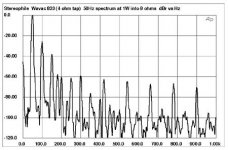
Attached is one of my old ones showing noise riding in from the AC power line while the power supply rectifier diode is conducting. If you do the arithmetic this amount of noise will increase the noise floor to a level that may be perceptible depending on the loudspeaker's sensitivity (efficiency) and the listening environment noise floor. (About 29 dB spl without any gain or power supply filter loss for a small cheap loudspeaker. 46 dB spl with a horn and 19 dB spl with a low efficiency unit.)
Yes there is filtering for the expected 120 hertz ripple but it in a lower production cost power supply is almost useless at 6,000 hertz where the hearing of humans is most sensitive.
There's been pictures that go about making scary looking impulses plenty. That's all well and good, but tells no one anything about, at the end of the day whether that shows up on the speaker terminals, where the rubber meets the road.
Is that what you're showing? Is this across the DC rail, or vdrop across the diode during conduction? (That would seem too low for the latter though, even on some of the lower vdrop schottkys)
PSRR is proportional to loop gain, to a large degree, so of course it falls off with frequency. Was that ever a question?
Demian--your question is why I asked about from end-to-end when everything is connected behind the same isolation transformer. Not either/or with actually managing the floating potentials/differential signaling.
Derfy,
Take an oscilloscope and look at the power supple rails yourself. Then look at the output.
I did, in my NAD mid-fi amplifier. Some mV of RF junk on the supply rails, absolutely nothing at the output, except some 500uV of 50Hz and 150Hz mains harmonics.
I think I’m ******, what should I do?
I will be in The Orient … quaint word … S.E.Asia (Bangkok) on Tuesday.
The company which built them for Monster still sells power conditioner products. I will give you feed back about them if any one wants to buy instead of DIY. I need to check and measure them. I have the network analyzer there to do it with. I shipped the same unit to them and it is in my office there. The engineering has been done for you and the build.
All the units from Monster were UL/VDE/CE approved. They have many features in them... sequential off-on-off, significant surge and spike protection and CATV cable protection etal. And line voltage meter +++
I dont make money on anything from them. I am there now for other reasons…. to help them organizationally and to do audio amplifiers. There were Monster branded/distributed audio power amps that were extremely well performing and bullet proof. They were all CFA and MOSFET OP.
Those came in stereo and multi-channel for surround. Great amps at great prices on eBay.
THx-RNMarsh
Last edited:
Mark.... new current loop probes on the way. various sizes.
Nice.
Now, do some real science....
")
Measure the total current flowing through one of your IC's. Clamp over the entire cable.
If it's a perfect system (which it isn't), you will find that the lower audio frequencies can be picked up by clamping over the IC.
And if your really good, you will find the same thing happening with your line cords. You will see lf audio content on the power cords if you clamp over all three conductors.. LF current that should be returning to the preamp via the IC, but doesn't. It takes the lower impedance path to return to the preamp.
jn
I did, in my NAD mid-fi amplifier. Some mV of RF junk on the supply rails, absolutely nothing at the output, except some 500uV of 50Hz and 150Hz mains harmonics.
I think I’m ******, what should I do?
is there a bridge or a cliff nearby?
-RM
Nice.
Now, do some real science....
Measure the total current flowing through one of your IC's. Clamp over the entire cable.
If it's a perfect system (which it isn't), you will find that the lower audio frequencies can be picked up by clamping over the IC.
And if your really good, you will find the same thing happening with your line cords. You will see lf audio content on the power cords if you clamp over all three conductors.. LF current that should be returning to the preamp via the IC, but doesn't. It takes the lower impedance path to return to the preamp.
jn
Been there. Done that. With power cords, too. I still have all equipment to it again.
One of the probes I will get is very tiny and it can used to localize the noise to a single pin or pcb trace.
Don't worry. I have several HP and TEK clamp-on type probes. Tek AM503, TEK P6042. HP and Fluke 43b also. Outputs can also be sent to a spectrum analyzer.
THx-RNMarsh
Last edited:
FWIW I think this is the kind of system Richard is talking about:
FELICIA - A DIY Balanced Power Conditioner
I have some old PA supply transformers (big) with lots of taps they should work here (step up/down are same ratio). Still looking for the $20 BOM.
Just for humor it is not practical to build an AC generator that produces a perfect sine wave. There have to be gaps in the armature to insert the windings. That results in distortion.
ES
Ed, I recommend you never try to get a job designing generators or motors.
That statement indicates "gaps" in magnetic design knowledge. People who design resolvers kinda know better.
Jn
Been there. Done that. I still have all equipment to it again.
One of the probes I will get is very tiny and it can used to localize the noise to a single pin or pcb trace.
THx-RNMarsh
Where's the data? Didn't get done if there's no data...
jn
I think I’m ******, what should I do?
You could save $350,000 for these.
Attachments
Absolutely.Typical of people to go to familiar safe territory when obvious issues are in front of you.
Looking at an amp and talking about line conditioning is a great case in point. Those amps do not exist in isolation. The network of connections between the boxes is the bigger issue and line conditioning will change the leakage currents but not eliminate them. Even 1000 dB psrr won't remove currents flowing across chassis.
is there a bridge or a cliff nearby?
You are too good for me, I give up.
- Status
- Not open for further replies.
- Home
- Member Areas
- The Lounge
- John Curl's Blowtorch preamplifier part III