The TH Coilcraft inductors on your 3251evm probably are an easier fit, maybe some Icecomponents fit. But first I would run test on your 3251evm or YJ3255 to see if you get same distorted waveforms at same power as FX amp.
you are good informed.
")
i have to do the measurments once again, as doctor warned me ...
post #565
thanks
chris
Thank you!!!!!hi shrek7
i found that...
chris
Thank you!!!!!
your welcome
but before you buy ask the experts here....irribeo and doctormord....etc...
saturation on the output.....
Hi yesterday i made a short measurement.
scope pics: - from top to buttom
yellow input signal on RCA -top
light blue Output + on the Rchannel -middle
purple Output - on the Rchannel - middle
blue opamp pin 1 or 7 on the opamps -buttom
psu ist the original 24V psu- LM317 is set to 20V. 8 ohms load each channel.
input is 1Vrms on both RCA in.
at the input socket of the PSU - out surface - i solder an extra pin to connect all GND of the scope probes.
psu is isolated from GND. - kind of Laptop brick..24V
first setup was 400hz to check the singal on the opmaps and give low volume. 5,18 V and 5,25V mearued with my DMM on the outputs.
my new Voltcraft VC320 is True RMs but just working up to 400hz...i got 0,65Amps
then i switched to 20khz
pic 1 - low volume 20khz...no saturation
pic 2 - low volume 20khz..no saturation..but zoomed for the outputs...
high volume means nearly max output , before clipping and about 1,5 amps
pic 3 - high volume 15khz --> saturated..opamps not!
pic 4 - high volume 20khz --> saturation ..opamps not
1 is this measurment correct done?
2 why is the input 1Vrms and on the outputs of theopamps i got about 267mVrms and at max 592mVrms?
chris
you are good informed.
i have to do the measurments once again, as doctor warned me ...
post #565
thanks
chris
Hi yesterday i made a short measurement.
scope pics: - from top to buttom
yellow input signal on RCA -top
light blue Output + on the Rchannel -middle
purple Output - on the Rchannel - middle
blue opamp pin 1 or 7 on the opamps -buttom
psu ist the original 24V psu- LM317 is set to 20V. 8 ohms load each channel.
input is 1Vrms on both RCA in.
at the input socket of the PSU - out surface - i solder an extra pin to connect all GND of the scope probes.
psu is isolated from GND. - kind of Laptop brick..24V
first setup was 400hz to check the singal on the opmaps and give low volume. 5,18 V and 5,25V mearued with my DMM on the outputs.
my new Voltcraft VC320 is True RMs but just working up to 400hz
...i got 0,65Ampsthen i switched to 20khz
pic 1 - low volume 20khz...no saturation
pic 2 - low volume 20khz..no saturation..but zoomed for the outputs...
high volume means nearly max output , before clipping and about 1,5 amps
pic 3 - high volume 15khz --> saturated..opamps not!
pic 4 - high volume 20khz --> saturation ..opamps not
1 is this measurment correct done?
2 why is the input 1Vrms and on the outputs of theopamps i got about 267mVrms and at max 592mVrms?
chris
Attachments
Last edited:
The UA8013 are working well, if you can solder them.
Some compact inductor data is compiled here:
http://www.360customs.de/wp-content/uploads/2016/10/inductor_cmp.png
Some compact inductor data is compiled here:
http://www.360customs.de/wp-content/uploads/2016/10/inductor_cmp.png
The UA8013 are working well, if you can solder them.
Some compact inductor data is compiled here:
http://www.360customs.de/wp-content/uploads/2016/10/inductor_cmp.png
thanks doc!

i found your list month ago........but i was afraid to post "your secrets"
so i guess the measurments are ok. thanks
what about the opamps--Question 2
sorry noob alarm
"Because differential". You measured the outputs with respect to ground.2 why is the input 1Vrms and on the outputs of theopamps i got about 267mVrms and at max 592mVrms?
Forget that:
"Because differential". You measured the outputs with respect to ground.
At what frequency did you checked this? If the circuit follows EVM design, the gain should be x1 at all.
With "592mVrms" you can't max out the TPA Chip.
Hi Doc
as you can see on the scope pics...15kHZ and 20khz.pic 3 and pic 4
@ max power of the amp = 20V psu (lm317 setting)
i try to explain:
the volume is about 12 o clock and the scope shows this strange sinus. if i go slightly with the volume up...lets say 1 o clock - i get the "clipping" = cutting the sinus on the top.
so this is the reason i said "max power" ..look at last pic Vpp is 17V............ slightly more and i got clipping.
so i have actually 2 issues:
1 saturation because of coils
2 clipping at approx 18V--- its ok for me...
thanks chris
coils saturation part 2...
i measured the coils DCR for all 4 on the V5 (white pcb)
its about 80-90mohms...the diameter is 13mm and they are really closed.. 15mm is the maximum for put 4 single coils instead this air coils.
8 ohm load...i try 4 ohms each channel but its the same sinus...or not really sinus wave...
scope pics: - from top to buttom
yellow input signal on RCA -top
light blue Output + on the Rchannel -middle
purple Output - on the Rchannel - middle
blue opamp pin 1 or 7 on the opamps -buttom
pic 1 400hz start to scatter .no clipping
pic 2 400hz start to clipping..2 ampere each channel...its 2 o clock
pic 3 6kHz ...strange form
pic 4 12kHz ...strange form
pic 5 15kHz ...strange form
pic 6 20kHz ...strange form
chris
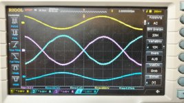
Attachments
-
 FX502spro_v5_1Vrms 20kHz output starts to be no sinus.jpg162.8 KB · Views: 66
 -
 FX502spro_v5_1Vrms 15kHz output starts to be no sinus.jpg160.1 KB · Views: 511
 -
 FX502spro_v5_1Vrms 12kHz output starts to be no sinus.jpg171.9 KB · Views: 517
 -
 FX502spro_v5_1Vrms 6kHz output starts to be no sinus.jpg151.6 KB · Views: 530
 -
 FX502spro_v5_1Vrms 400hz output starts to clipping_2 Ampere.jpg173.1 KB · Views: 535
 -
 FX502spro_v5_1Vrms 400hz output starts to scatter this is no clipping.jpg176.7 KB · Views: 546
...choose coils..
Hi doc
if i check your list i have a question:
is the red marked Würth 7443551730 (bad toleranz bad THD) worse then the air coils?
myidea is to avoid costs and delivery time from digikey or external coilcraft...etc.
this 7443551730 is cheap and quick available....
thx
chris
Hi doc
if i check your list i have a question:
is the red marked Würth 7443551730 (bad toleranz bad THD) worse then the air coils?
myidea is to avoid costs and delivery time from digikey or external coilcraft...etc.
this 7443551730 is cheap and quick available....
thx
chris
So the YJ and EVM sines are superior ?
AAAAH...so you mentioined i have to order more ...
no i didn t test the other boards yet...
but you really think that the EVM board need upadtes?
You might get funny shaped sinewaves with all classD amps you measure, if so, improving measurements could have higher priority than changing parts
...hmm...i am confused.
because i got not clear answer to my latest measurements.so you mean that with the math function on my scope i get the real sum (A//B)
of the output signal? ...i have to check...
or do you mean shrek7 topic with his TPA3251EVM? ...
..sorry to badger you....
Hi
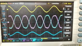
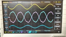
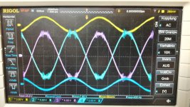
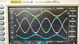
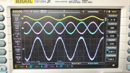
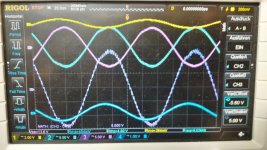
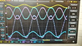
i did the measurements again. with the output + (ch2) and output - (ch3) with my scope and the math function.
4 ohms load each channel. 24 psu.
it looks better but at 9 kHz its start to be no really sinus. is it bad in SQ??
i am really on my end of understanding what should i do. are the measurements wrong....which direction should i go
pic 1 6khz
pic 2 9khz
pic 3 15khz
pic 4 20khz
chris
Hi
i did the measurements again. with the output + (ch2) and output - (ch3) with my scope and the math function.
4 ohms load each channel. 24 psu.
it looks better but at 9 kHz its start to be no really sinus. is it bad in SQ??
i am really on my end of understanding what should i do. are the measurements wrong....which direction should i go
pic 1 6khz
pic 2 9khz
pic 3 15khz
pic 4 20khz
chris
Attachments
-
 FX502spro_v5_1Vrms 20kHz output with ch2-ch3 math function.jpg189 KB · Views: 71
 -
 FX502spro_v5_1Vrms 15kHz output with ch2-ch3 math function.jpg169 KB · Views: 64
 -
 FX502spro_v5_1Vrms 9kHz output with ch2-ch3 math function.jpg174.8 KB · Views: 69
 -
 FX502spro_v5_1Vrms 6kHz output with ch2-ch3 math function.jpg176.4 KB · Views: 72
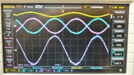
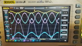
as comparison TPA3255 YJ baord blue....
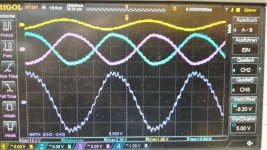
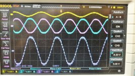
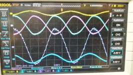
Hi
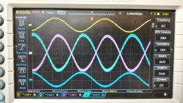
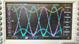
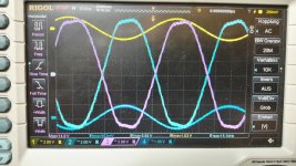
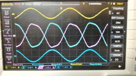
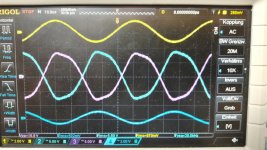
i did the measurements with my 2 amps blue YJ TPa3255 board. 31V psu (rigol dp832) 400mVrms input on both rca. 4 ohms load each channels.
scope pic from top to buttom
yellow input rca channel 1
blue and pruple ch2+ch3 output l + and output -
math function ch2-ch2
dark blue pin 1 on the op amps
pic 1 6khz
pic 2 9khz
pic 3 15khz
pic 4 20khz
so its looks the same for me. so the lessons learnt is:
for me the tpa3255 boards sound better...but you cant see it on the scope sinus waveform....
next step to improve the fx502spro irribeo??
chris
Hi
i did the measurements with my 2 amps blue YJ TPa3255 board. 31V psu (rigol dp832) 400mVrms input on both rca. 4 ohms load each channels.
scope pic from top to buttom
yellow input rca channel 1
blue and pruple ch2+ch3 output l + and output -
math function ch2-ch2
dark blue pin 1 on the op amps
pic 1 6khz
pic 2 9khz
pic 3 15khz
pic 4 20khz
so its looks the same for me. so the lessons learnt is:
for me the tpa3255 boards sound better...but you cant see it on the scope sinus waveform....
next step to improve the fx502spro irribeo??
chris
Attachments
-
 TPA3255 original amp2 400mVrms 6kHz output with ch2-ch3 math function.jpg181.1 KB · Views: 89
 -
 TPA3255 original amp2 400mVrms 9kHz output with ch2-ch3 math function.jpg162 KB · Views: 79
 -
 TPA3255 original amp2 400mVrms 15kHz output with ch2-ch3 math function.jpg167.4 KB · Views: 62
 -
 TPA3255 original amp2 400mVrms 20kHz output with ch2-ch3 math function.jpg186.4 KB · Views: 76
- Home
- Amplifiers
- Class D
- TPA3250 somebody is listening?