You’re correct there was no fuse in the 24 V line to the amp. I was impatient and just wanted to get things halfway wired together to see it up and running to work out the bugs because I have to manufacture a back panel to mount all my connections and I wasn’t ready for that yet. Thank you for giving me the fuse amperage size I will be installing those tonight I’d rather see a small flash have a fuse then a large flash and smoke of transistors and resistors . As for the Transformers they came with their own built-in fuses but they did not blow even though my wattmeter that I was plugged into show A wattage draw 416 W.
I have an eye towards buying two kits to use them as monoblocks though from what I understand this can only be done via the balanced XLR input. My issue is that my preamp (a Heathkit AA-1800) only has unbalanced RCA outputs. Is there a way to make these new versions of the ACA work as monoblocks without a balanced signal? Or is there an easy, noise free way to go from an unbalanced output to a balanced input for this particular application?
Yes. It requires 1 resistor and 1 RCA jack. I need only to build it and photograph it, and it will be part of the guide.
If you are interested in Monoblocks but only have RCAs, you'll be fine, go ahead and order 2 ACA kits.
")
You’re correct there was no fuse in the 24 V line to the amp. I was impatient and just wanted to get things halfway wired together to see it up and running to work out the bugs because I have to manufacture a back panel to mount all my connections and I wasn’t ready for that yet. Thank you for giving me the fuse amperage size I will be installing those tonight I’d rather see a small flash have a fuse then a large flash and smoke of transistors and resistors . As for the Transformers they came with their own built-in fuses but they did not blow even though my wattmeter that I was plugged into show A wattage draw 416 W.
2A T fuse pr side should do it but 3.15 T has more limit agsint that fuse blows without a fault but gives less protection against a real fault.
I also use a vario transformer first time I apply power with an A-meter so I slowly apply voltage. If it draws much more current that it should I stop and nothing has been damaged.
part 2 Snap,Pop, Flash 4th time replacing transistors
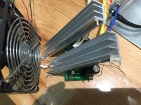
this time I removed the possibility of a short to ground of the transistors. I placed each transistor on it's own heat-sink. Even without insulation pads it make no difference, transistors are not touching any thing and a fan is blowing cool air over the heat-sinks and circuit board.
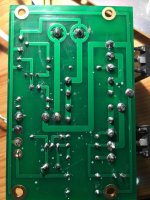
As soon as I plugged in the power into my watt meter it spiked up to 200W and I immediately pulled it. the only heat developed was the resistors on the power supply, transistors and power resistors on the amp board just mild warm. The photo under the circuit board so you can see the quality of solder nothing bridged. This time looking at the insulating pads you can see they did not get hot, no brakes or metal filings.
1:What should my next step to test?.
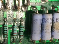
2:Should I increase the voltage on C2 from 25V to 35V because i'm using 24V instead of 19V?.
By the way the sound difference between the 19V computer brick power supply and the separate toroidal transformers mono power into the DIY UPS is worth the extra time and money
this time I removed the possibility of a short to ground of the transistors. I placed each transistor on it's own heat-sink. Even without insulation pads it make no difference, transistors are not touching any thing and a fan is blowing cool air over the heat-sinks and circuit board.
As soon as I plugged in the power into my watt meter it spiked up to 200W and I immediately pulled it. the only heat developed was the resistors on the power supply, transistors and power resistors on the amp board just mild warm. The photo under the circuit board so you can see the quality of solder nothing bridged. This time looking at the insulating pads you can see they did not get hot, no brakes or metal filings.
1:What should my next step to test?.
2:Should I increase the voltage on C2 from 25V to 35V because i'm using 24V instead of 19V?.
By the way the sound difference between the 19V computer brick power supply and the separate toroidal transformers mono power into the DIY UPS is worth the extra time and money
Attachments
If you are running 24 volts, i hope you added one extra resistor (2k2), and changed values of two other resistors as per post #105.
Its possible you exceeded limits of jfet, now even you added new good outputs, amp is not working right, current all over.
Check each transistor.
I built few ACA, even turbo version, but i have 5x the heatsink plus fans.
Good luck.
Its possible you exceeded limits of jfet, now even you added new good outputs, amp is not working right, current all over.
Check each transistor.
I built few ACA, even turbo version, but i have 5x the heatsink plus fans.
Good luck.
soldering is still all over the place , regarding quality
you simply can't beat the physics , especially if lacking in luck department
find someone skilled enough , to solve your problems
SF is big city , there must be some Greedy Boy near you
xperience shows , with cost of 6pack and some gasoline , there is a chance to find friend for life
you simply can't beat the physics , especially if lacking in luck department
find someone skilled enough , to solve your problems
SF is big city , there must be some Greedy Boy near you
xperience shows , with cost of 6pack and some gasoline , there is a chance to find friend for life
Pass DIY Addict
Joined 2000
Paid Member
ThermalAlchemy - I agree with what everyone said above.
Edit: Apparently, I hit "reply" before I realized there was another page of discussion.... oops...
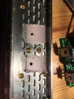
That irregular surface with the oval holes has many edges. If the mosfet is not *PREFECTLY* level with the mounting surface, or any of those oval holes have even the *SLIGHTEST* of a raised lip around the edges, you are likely to have cut-through in your SilPad and then the mosfet grounds to the sink and causes things to burn up.
The image you have where you removed this metal lattice work is a MUCH better approach, but I would go one step further. Remove this metal lattice from the sink that it is attached to. Then, take some 400 grit wet/dry sand paper, wrap it around a small flat metal block (never just use your fingers), apply some lubricant (water, oil) and do some sanding on that screw hole to make sure there is not a raised lip around the edge that will also cut through your next SilPad and ground the mosfet again.
Surface prep for mounting mosfets is *VERY* important.
Edit: Apparently, I hit "reply" before I realized there was another page of discussion.... oops...
That irregular surface with the oval holes has many edges. If the mosfet is not *PREFECTLY* level with the mounting surface, or any of those oval holes have even the *SLIGHTEST* of a raised lip around the edges, you are likely to have cut-through in your SilPad and then the mosfet grounds to the sink and causes things to burn up.
The image you have where you removed this metal lattice work is a MUCH better approach, but I would go one step further. Remove this metal lattice from the sink that it is attached to. Then, take some 400 grit wet/dry sand paper, wrap it around a small flat metal block (never just use your fingers), apply some lubricant (water, oil) and do some sanding on that screw hole to make sure there is not a raised lip around the edge that will also cut through your next SilPad and ground the mosfet again.
Surface prep for mounting mosfets is *VERY* important.
Last edited:
Thank you all for your input it looks like I have several things to do . I did not put the 2.2K resistor thank you for pointing me towards the post for the 24 V . On the last third set of transistors I did true the surface of the heat sink so it was flat on the third set. Since this is been used in my class for electronics as part of my class project and I work full-time daily this board will be put off to the side to be diagnosed later and it’s a good thing I ordered four more ACA boards sitting in my parts box.
At the moment, any NuTube project would be for a separate box.
There are no plans for an ACA with a Nutube inside.
Thank you. I do appreciate that. I plan to buy the ACA being released, but wanted to make sure a future revision wouldn't prompt me to sell it and buy the newest (I have neither the time nor money).
Pass DIY Addict
Joined 2000
Paid Member
When the MOSFET is mounted it is good to check the insulation using an ohm-meter set to Mega Ohm. It should show "infinite".
This is EXCELLENT advice and part of my SOP (standard operating procedure) for mounting transistors to sinks. Check for continuity between each pin and the sink. Should come up "open loop" each and every time.
This is EXCELLENT advice and part of my SOP (standard operating procedure) for mounting transistors to sinks. Check for continuity between each pin and the sink. Should come up "open loop" each and every time.
Yes, and it seems that the "back" of these MOSFETs is connected to the Drain pin so the center PIN when looking at a Vishay data sheet for IRFP240. But probalby good to check between all three pins to the heatsink (have to press hard with the probe PIN to get through black coating and oxide layer). And before the MOSFETs are soldered to the PCB and mounted as the PCB center screw makes connection from GND on PCB to heatsink.
Yes, check this one by X:
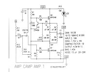
Amp Camp Amp - ACA
Thank you.
Pass DIY Addict
Joined 2000
Paid Member
But probalby good to check between all three pins to the heatsink (have to press hard with the probe PIN to get through black coating and oxide layer).
If you've tapped a hole in the sink, just use the mounting screw as your reference point...
- Home
- Amplifiers
- Pass Labs
- Amp Camp Amp - ACA