three sets of transsistors (Snap Pop Flash Magic Smoke)
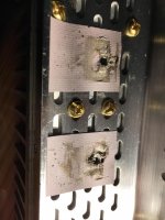
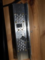
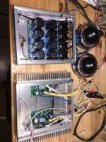
I didn’t want to ask for help this time I was determined to fix it but after three times it’s time to call in the Calvary. It worked great for three days after completion. Just finished building the Fostex BK20 horn loaded speakers for this amp that I read were recommended. Just finish building the universal power supply from DIY audio, got two toroidal transformers 200 VA each, running the system at 22.8 V I don’t know why they would not go to exactly 24 V under load. On day three while I was listening to music there was a snap pop and a flash and Magic smoke started coming off the 3 W Panasonic resistors from the power supply and the 3 W resistors and transistors of the amp board. Found a ground center leg I think it’s called the gate on the transistor of Q2 to chassis. See attached photos you can see the tiny gold arc mark on the back of a transistor and how the pink insulating pads seem to crush away and dissolve when they get hot. I replaced the transistors put some fresh insulating pants turned it on and it worked, “ for about five minutes”. Snap pop flash magic smoke again. Same thing then I determined because I was trying to fasten the transistors to the computer case that had holes sluts cut into them for letting air through May have been uneven so when tightening it pinched through the insulating material. This time I cut holes into the case to mount the transistors flat on the recycled heat sinks I got from air conditioning inverters and I cut down to size. Installed the third set of transistors plugged it in it worked but only about five minutes then more magic smoke with the flash. I was a mechanic most of my life and I’m in air-conditioning now I’m used to diagnosing things with repair manuals with troubled trees and pin out schematics for taking voltages and conductivity readings . But for this little amp camp board I take it there’s no written manual. The signal the power and the speaker wires are recycled off my job site there what we use for signal cables there shielded and have a draw wire ground we use them up to 1000 feet in length to carry our signal so I figured it would be good in this application for only about 9 inches a little overkill.
Was thinking for now it may be faster for me to just build up another board I have for spares, diagnose later.
Attachments
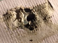
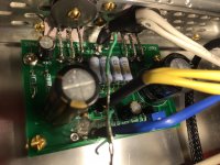
Looking at the photos your issues appears to be the interface between the back (flat metal) of the Mosfet, the insulator, and the heatsink fact that it attaches to - all of that must be very flat to get the heat out of the fet and into the heatsink. Things were getting too hot, the interface failing, then the mosfets were shorting out, pulling lots and lots of current, discoloring resistors and burning transistors.
Cut away more of the perforations, (you were totally on the right track!) you don't actually need all of those screws holding the heatsink to the chassis. Clear enough space so none of the perforated metal touches the fet, insulator, or fender washer. Make sure the heatsink itself is flat and smooth. If it's not, the heat will have to conduct through greatly reduced area, making the mosfet itself really hot.
You need new insulators, those are dead. Make sure the fets, insulator, and heatsink face are all clear of metal crumbs or shavings when putting it all together.
Last edited:
3rd time it was cleanand flat
3rd time it was clean and flat, nothing touching, I ohm first to make sure no short before applying power.
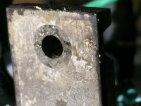
question, is there a problem with this insulator pads if tighten too much it pinches through. is mica tougher?. I'm sure I did not over tighten 3rd time. I chamfered the hole I drilled for the screw. I drew a flat razor across the surface to takes down any high spots and confirm it was clean and flat. There is a good 1mm+ clearance all the way around the transistor.
My knowledge is not yet enough to fully understand, but is there a component that could get damaged by the first two melt downs and cause thermal runaway of the transistor?.
My next test on the 4th pair of transistors I will attach individual heat-sinks no pads separated apart so they can't short, run a fan on them for a day off the chassis. When they pass that test then I will remount them. I'll keep you updated. thanks.
PS. Are MICA pads more durable?
3rd time it was clean and flat, nothing touching, I ohm first to make sure no short before applying power.
question, is there a problem with this insulator pads if tighten too much it pinches through. is mica tougher?. I'm sure I did not over tighten 3rd time. I chamfered the hole I drilled for the screw. I drew a flat razor across the surface to takes down any high spots and confirm it was clean and flat. There is a good 1mm+ clearance all the way around the transistor.
My knowledge is not yet enough to fully understand, but is there a component that could get damaged by the first two melt downs and cause thermal runaway of the transistor?.
My next test on the 4th pair of transistors I will attach individual heat-sinks no pads separated apart so they can't short, run a fan on them for a day off the chassis. When they pass that test then I will remount them. I'll keep you updated. thanks.
PS. Are MICA pads more durable?
Yes I used new pads I bought the little kit for $19 that came with many extra pads. Yes I know they are electrically isolating because the back part of the transistor is hot. I was actually going to run them separately on small separate individual heat sinks isolated off the chassis. The heat sinks were going to be individual separate from each transistor so there’s no possibility for shorting during my burn in test, prior to remounting the board back into the chassis on the singular main heat sink.
Ah, I got distracted writing my long email above...
That's something for later in the year, certainly after we have migrated diyAudio onto the next platform (which I'd like to have completed within the next 2 months, but will probably end up being 4).
If you don't mind my asking, what platform are you considering? I'm a software engineer, and take an interest in this sort of thing.
Hi Everyone. This is my very first post here on DIYAudio. Thank you for the cool and awesome forum!
I built the ACA a few weekends ago and I am very happy with the results. This is also my first electronics build like this. I learned a lot of new skills. My solder joints are not bad for a first go at this. ;-)
@6L6 thank you for the excellent build guide. It was super easy to follow and I was up and running in about a day and a half.
I believe that 6L6 is correct about the perf mounting surface. The mounting surface must be continuous material without the perf holes. Those hole allow for local hot spots on the mosfet, burning thru and making a conductive path. As 6L6 suggested, cut the perf area where the mosfets mount. This gives a flat and smooth mounting surface making for evenly spread heat transfer from the back of said mosfet to heat sink. This will eliminate those local hot spots.
Jason / Mark - I was only half joking about the custom engraved face plates, and had I actually Googled the part number you listed for the Meanwell, I wouldn't have needed to ask that question - so, sorry for the time wasting distraction.
While some folks might want to eschew power switch altogether, I can certainly understand wanting it on the front panel.
While some folks might want to eschew power switch altogether, I can certainly understand wanting it on the front panel.
newbie question
Hi. I'm planning to purchase an amp camp amp kit (or two) when the presale begins this week and build my first amplifier. I have some experience soldering, as I work in sound recording for film/TV and have made/repaired XLR cables before, although I will be the first to admit that my technical knowledge is limited (basically, while I don't always understand the implications of what I'm doing, I'm good at following instructions and making things work.) I have an eye towards buying two kits to use them as monoblocks though from what I understand this can only be done via the balanced XLR input. My issue is that my preamp (a Heathkit AA-1800) only has unbalanced RCA outputs. Is there a way to make these new versions of the ACA work as monoblocks without a balanced signal? Or is there an easy, noise free way to go from an unbalanced output to a balanced input for this particular application?
I should that at this point switching preamps is not an option, for a variety of reasons. Thanks in advance for any help.
I didn’t want to ask for help this time I was determined to fix it but after three times it’s time to call in the Calvary. It worked great for three days after completion. Just finished building the Fostex BK20 horn loaded speakers for this amp that I read were recommended. Just finish building the universal power supply from DIY audio, got two toroidal transformers 200 VA each, running the system at 22.8 V I don’t know why they would not go to exactly 24 V under load. On day three while I was listening to music there was a snap pop and a flash and Magic smoke started coming off the 3 W Panasonic resistors from the power supply and the 3 W resistors and transistors of the amp board. Found a ground center leg I think it’s called the gate on the transistor of Q2 to chassis. See attached photos you can see the tiny gold arc mark on the back of a transistor and how the pink insulating pads seem to crush away and dissolve when they get hot. I replaced the transistors put some fresh insulating pants turned it on and it worked, “ for about five minutes”. Snap pop flash magic smoke again. Same thing then I determined because I was trying to fasten the transistors to the computer case that had holes sluts cut into them for letting air through May have been uneven so when tightening it pinched through the insulating material. This time I cut holes into the case to mount the transistors flat on the recycled heat sinks I got from air conditioning inverters and I cut down to size. Installed the third set of transistors plugged it in it worked but only about five minutes then more magic smoke with the flash. I was a mechanic most of my life and I’m in air-conditioning now I’m used to diagnosing things with repair manuals with troubled trees and pin out schematics for taking voltages and conductivity readings . But for this little amp camp board I take it there’s no written manual. The signal the power and the speaker wires are recycled off my job site there what we use for signal cables there shielded and have a draw wire ground we use them up to 1000 feet in length to carry our signal so I figured it would be good in this application for only about 9 inches a little overkill.
Was thinking for now it may be faster for me to just build up another board I have for spares, diagnose later.
You don't have a rail fuse at the 24V? .....e.g. a 2A or 3.15 A (F)ast fuse?
I think such a fuse could have saved you for at lot of smoke.....
The SM PSU probably have a built-in overload protection. A linear PSU with a lot of uF has a lot of energy so I think good to have some kind of protection.....if you have a fuse at the 24V I wonder why it did not blow....?
bm2352 - take a look at THAT Driver: Differential line driver / preamp
for the pre-amp, did you mean AP-1800 ?
There might be enough real estate inside to shoe-horn some type of balanced output stage.

for the pre-amp, did you mean AP-1800 ?
There might be enough real estate inside to shoe-horn some type of balanced output stage.
If you don't mind my asking, what platform are you considering? I'm a software engineer, and take an interest in this sort of thing.
Not at all. IPB (Invision Power Board) or XF (XenForo), most likely XenForo due to its flexibility. Don't post a reply in this thread though, the right place would be diyAudio will be down this Sunday/Monday for upgrades or Jason it's time for an immigration....
I have an eye towards buying two kits to use them as monoblocks though from what I understand this can only be done via the balanced XLR input.
Don't know if I'm missing something in your question, but the ACA can be built as monoblocks if you put the PCB's in separate enclosures and use two power supplies. It can even be done with one power supply if you really want to. I'm running my dual monoblock ACA (both in the same chassis) from one PSU but via a cap multiplier to ensure proper channel separation.
You could also use two ACA kits and use them in bridged monoblock mode. Maybe that's what you're referring to. But even then, I'm pretty sure that you don't need balanced inputs. The option is there, though.
Yes. My question was referring to buying two kits and using them as monoblocks. It seems as though I misunderstood the necessity of using the XLR input to do this. Re: chrisb, yes I meant the ap-1800 you have pictured there. There is plenty of space inside, though I fear "shoe-horning" in a balanced output stage is perhaps beyond my skillset. Thanks for the replies.
Things are still being discussed but this is what it looks like:
Parts Kit
* Upgrading rear toggle switch to beefier one (Parts Express 060-538) with 6.4mm dia hole (hopefully we can do the anti-turn washer "dimple" in the rear panel, just a nicety)
* Upgrading rear DC jack to beefier one (Digikey 839-1292-ND) with 11mm dia hole
* Upgrading PSU to a Meanwell 24V 5A GST120A24-P1M (This will be available for purchase directly from the diyAudio store with a bundled IEC power cable)
* Adding "classic" round black ACA front power switch
* Including some blue LEDs as well as the red
* Including XLR jack
Chassis
* Middle of the front panel will have a 20mm hole for the new power switch (that will for "modding" purposes also support the commonly available 19mm vandal type switches which have a 22mm bezel, and available in momentary/latching/capacitive/piezo, customisation options a-plenty)
* Offering the chassis in black and silver
* Offering the chassis with and without front power switch hole (for people that either like a clean front look, rear power switch or want a matching chassis for their March chassis)
* Please note - these changes might... change before the pre-sale starts, or even slightly change before we ship. Let's say 85% confidence at this stage this will be the change set.
Yep, that was my fear. There seemed to be some indication that a Nutube buffer project might be in the works. It seems like that is not a part of this release. Would a Nutube buffer be a stand alone project... or something integrated into a future ACA?
This is where our plans are now, But as has been mentioned above, things aren’t completely fixed in stone:
Most of the changes are quite small tweaks. Different DC jack and switch, XLR connector, front switch. The PSU in the original kit was a quite inexpensive one so there is almost no loss there. The new PSU is a significant expense , and will only be sold separately, and not included in the new kit box, so is available to all as an upgrade. The only hard to implement change is the front panel drilled for the switch , but as Jason mentioned, if you want a second ACA with a front panel to match your first one, that will be an option.
At the moment, any NuTube project would be for a separate box.
There are no plans for an ACA with a Nutube inside.
Last edited:
Yep, that was my fear. There seemed to be some indication that a Nutube buffer project might be in the works. It seems like that is not a part of this release. Would a Nutube buffer be a stand alone project... or something integrated into a future ACA?
I'm pretty sure that the ACA will remain as the "ideal amp building gateway drug" - the easiest possible way to build a beautiful Class A amp. Also the simplest circuit, the least number of parts, the least complicated and fastest build, and the lowest cost. That's a great niche for it to fill and it fills it magnificently (thank you Nelson!).
There's lots of other things planned for the future, but one thing at a time...
While I'm here and we're talking about making life simple for beginners, I should mention that we're starting a new part of diyAudio called "diyAudio Guides". It's in beta at the moment at and the only guide so far is the ACA build guide. Once we iron out the kinks, we'll be opening it up for everyone to contribute. You can read more about it in the announcement I just made - diyAudio Guides, and here's a direct link to the Amp Camp Amp Build Guide in diyAudio Guides.
Last edited:
- Home
- Amplifiers
- Pass Labs
- Amp Camp Amp - ACA