Hello guys, my last post here was more than 5 years a go when I started populating my mezmerize board, then it went to a shelf to byte the dust missing chassis , Rca's, input switch selector and power entry filter module.
Started building this, because in that time managed to finish Aleph 2 with the help of a lot of people like you guys, and I ask them which Pre is going to be a good match for my Amp and they point me to this thread.
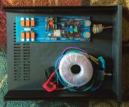
so I'm posting some pictures of the setup and to start asking some question to a happy ending .
1- one of the missing part was an IRF240 , just order at the time that I did with the others but it was back order then and I think is back order today , going to use IRF244 (have a lot of them to be use in Aleph2).
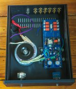
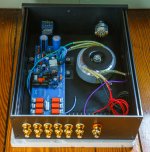
2- When I was working on the chassis I was planning to mount vol. pot and input selector directly to front panel then baaaang, they do not fit properly , I have to use a small extender, if you can please advise on this one is going to be apreciated.
3- I need to order power entry filter module, is 3A ok, it has power switch and fuse built in but don't know if comes with the fuse, anyway going to order a couple of them. My transfo is 50va , is 0.5 A ok?
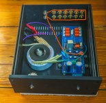
4- In one of the pictures you can see how I'm, going to wire the RCA's, some advise here too. and finally for now
5- Can I start testing to see if the led's working without any fuse connected ?
Thanks in advance.( pictures too big )
Started building this, because in that time managed to finish Aleph 2 with the help of a lot of people like you guys, and I ask them which Pre is going to be a good match for my Amp and they point me to this thread.
so I'm posting some pictures of the setup and to start asking some question to a happy ending .
1- one of the missing part was an IRF240 , just order at the time that I did with the others but it was back order then and I think is back order today , going to use IRF244 (have a lot of them to be use in Aleph2).
2- When I was working on the chassis I was planning to mount vol. pot and input selector directly to front panel then baaaang, they do not fit properly , I have to use a small extender, if you can please advise on this one is going to be apreciated.
3- I need to order power entry filter module, is 3A ok, it has power switch and fuse built in but don't know if comes with the fuse, anyway going to order a couple of them. My transfo is 50va , is 0.5 A ok?
4- In one of the pictures you can see how I'm, going to wire the RCA's, some advise here too. and finally for now
5- Can I start testing to see if the led's working without any fuse connected ?
Thanks in advance.( pictures too big )
Attachments
Hi JP: You definitely should have a fuse on the transformer primary just in case. Even better, for a couple of dollars build a dim bulb tester. Get an electrical box and outlet and a simple light fixture, and wire it so ablight bulb (incandescent) is in series with the mains line. Plug into that. If everything works you should see the bulb glow briefly as capacitors charge at turn on, then no more than a dim glow. If you have a short the bulb will glow brightly, and since the bulb will be dropping voltage it will limit current into your circuit, saving components and possibly you property and life. (props to AndrewT) You can find wiring diagrams for the dim bulb circuit with a quick search.
Too bad about that thick front panel, I think there are bushing kits you can get to mount your switch and volume pot.
Too bad about that thick front panel, I think there are bushing kits you can get to mount your switch and volume pot.
Last edited:
....I saw a post on how to build a dim bulb tester I think a saved it....
Instructive video how to build superb bulb tester

DIY bulb tester
Attachments
Thanks Nezbleu, is this better than a Variac, I have one but I saw a post on how to build a dim bulb tester I think a saved it. Thanks
Variacs are great. The bulb tester has the advantage that it limits current as well as voltage at the load. The more current the load passes, the more voltage drops across the bulb, and the brighter it glows. Do you get a visual indicator before anything is damaged.
Regarding your other questins:
You don't need a power inlet filter, though I like them and used one in my build. 3A should be more than enough. (Check out Apex Jr they have some inexpensive ones on their "clearance" page.)
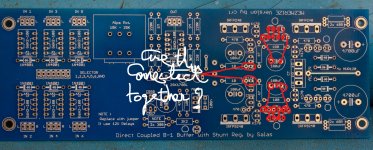
For the RCA wiring you should have the female connectors to match the 7 male connectors on the board, as well as the one that connects to the selector switch. Each pair of RCAs will connect to a 3pin connector, LGR the center pint is the shared ground.
You don't need a power inlet filter, though I like them and used one in my build. 3A should be more than enough. (Check out Apex Jr they have some inexpensive ones on their "clearance" page.)
For the RCA wiring you should have the female connectors to match the 7 male connectors on the board, as well as the one that connects to the selector switch. Each pair of RCAs will connect to a 3pin connector, LGR the center pint is the shared ground.
Thanks Nezbleu, I managed to built the dim bulb tester and fired the Mezmerize but the group of LED's from the IRF9240 (is this the positive side?) did not lit at all. Took some measurements : across 2x10R=1.65 vdc (irf244) 2x10R = -1.46 vdc (irf9240) V+ =0.625 vdc V- = -9.36 vdc across 100R = -0.52 vdc (irf244) , acroos 10R = -0.20 mv across 100R = 0.49 vdc ( irf 9240) , across 10R =-0.00 mv 7812 In to G =22 vdc out to G =11.91 vdc In to Out =10.11 vdc Across 47R =-0.00 (9240) Across 47R = -0.2 mv I did change Irf 9240 close to that group of LED's but did not fix the problem. Going to unsolder the led's. What do you think guys ? Thanks in advanced.
Last edited:
Really do not know , ccs is through the 2x10R resistors? then when I check thje LED's in diode mode they are going to lit if they are good? Thanks
Yes, CCS current in each polarity supply is indicated by the voltage drop across each 10R resistor. If your DMM has the capability to light up an LED in diode mode testing you will know it either from its manual if it states more than 1.5V test voltage in that mode or by just trying it on a spare red LED first. Red probe to LED's anode, black to cathode. If it can do it, then go across each installed LED with no need to desolder it first. In that way you will know if all can light up and if their polarity is good. One or more may not light because dead or lights up the other way around so its reversed. Or the whole string of LEDS has been installed in reverse, whatever mistake you will find out. Do that testing when power is off in the dcb1.
Thanks Salas and Nezblue, well apparently my DMM do not turn led's on and you said have to measure across the LED but when I measured across got OL on the meter, I did this with the LED's that turned on, but if measure from one LED to another LED I get 0.00. Sorry for ignorance but I'm really confuse . On the photos I show you how I did the measurements.Thanks again.
Attachments
Hello Salas, I did the test , 3 LED's were good , the other two were very dim and when I touched for second time (just touched not too much time) I heard small pop up , they don't lit anymore. Now to replace this 2 LED's just chose 2 more or do I have to measure them. Thanks in advance.
 More matching effort is for the Hypnotize.
Hello Salas, I did solder new LED's but still no luck here. I measured BC550, it is 0.1, going to replace it for another one (have to order) then checked the mosfet and not getting the 3.5 to 4 v here , but I already changed this when I replaced the LED's, don't know but this mosfet are kind of delicate.
- Home
- Amplifiers
- Pass Labs
- Mezmerize DCB1 Building Thread