By your distorted definition of distortion it is everywhere, you amplify it, you distort it, you attenuate it, you distort it. I will stick to the accepted definition of distortionIf you look at the term distortion in it's basic meaning, output signal deviating from input signal, the higher number reading on the meter does mean more distortion of the signal. The signal has changed.
Maybe my definition is wrong, it wouldn't be the first time. I go by this one. Distortion - Wikipedia
Hum, I read this thread from the beginning and for the study of a phenomenon of measurement of THD by vzaichenko I see that everyone goes from his little explanation and in the end it is to understand nothing more.
My question:
Do you think it's so important?
Because after all it will have to attack the speakers, connectors, the environment, etc ... And on paper never your measurements will satisfy you.
Personally that's what I hear that matters to me and the measures have little interest.
But it seems that more a wire, a connector, etc ... is expensive and the sound of an amplifier is good.
Maybe my definition is wrong, it wouldn't be the first time. I go by this one. Distortion - Wikipedia
The thread is about harmonic distortion
The thread is about harmonic distortion
Yes, and in my experience (limited in audio) THD measurements always rise considerably when any other type of distortion is present.
Excellent. It conducts electricity. Although as an observation, Kimber's speaker wire is braided rather than twisted.
I don't, given that the laws of physics our universe is obliged to conform with dictate that it doesn't. The signal couldn't give two hoots what way the wire is drawn.
Thanks for correcting me. I was being a little ironic too.
Noise is 'parasitic interference, or background floor of distortion, it is a group of nearly all frequency together as THD floor.
Distortion is the creation of harmonics from a signal.
Attenuation is the reducing of the signal amplitude.
In the tests we have an increase in THD of the signal which is distortion.
I appreciate they influence one another, but I don't see how a change in frequency response due to the speaker wire would cause much of a change in the THD let alone a considerable rise.Yes, and in my experience (limited in audio) THD measurements always rise considerably when any other type of distortion is present.
Your interpretation is misleading.In the tests we have an increase in THD of the signal which is distortion.
The measured distortion shows nothing more than distortion made by the loudspeaker.
Do see the results with a dummy load ( instead of a loud speaker ). They show NO distortion made by the cables or the load. That is because, the cables and the load are linear.
The tests with a loudspeaker load, reveals the distortion made by the loudspeaker, made because it is non linear.
The measurements do prove "Speaker cables don't influence harmonic distortion".
I appreciate they influence one another, but I don't see how a change in frequency response due to the speaker wire would cause much of a change in the THD let alone a considerable rise.
What do you think the spectrum of a 20k THD test will look like?
Hi All,
I think I understand what Pavel (BesPav) was trying to explain here.
Let's simplify the setup, assuming we've got an ideal amplifier (Zout = 0) and ideal connection terminals. Let's also simplify the complex Zcable and Zload to pure resistance. Zcable is linear, Zload is not linear.
Considering Zcable + Zload as a voltage divider, we can easily see that influence of Zload's non-linearity is proportional to Zcable / (Zcable + Zload).
Assuming Zload is a constant, the level of non-linearity, seen at Zload is proportional to Zcable. The lower Zcable -> the lower non-linearity is seen at Zload.
Meaning, the better the cable is -> the less distorted signal (Voltage) is seen at the speaker terminals.
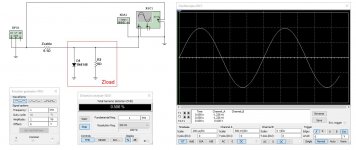
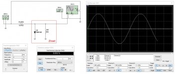
A simple simulation, using a diode as a source of non-linearity, is shown in the pictures:
1) Zcable = 0.1R, THD at the load = 0.506%
2) Zcable = 0.01R, THD at the load = 0.055%
Conclusion: assuming the amplifier (linear enough) and the speaker (rather non-linear) are the given constants, we can minimize the speaker's non-linearity effect by using a better (lower Z) cable.
Note1: if the amplifier is not good enough - not linear enough, not low-Zout enough, not providing enough current for driving the speaker at certain swing/frequency - that's a different kind of problem.
Note2: even if we see the voltage at the speaker's terminals being rather low-distortion, that does not mean the acoustic distortion is also that low - a speaker as a transducer is non-linear anyway.
Note3: the higher the quality of the amplifier and the quality of the speakers are - the higher influence of the speaker cables on the quality of sound reproduction will be observed.
Excellent material on the speakers' non-linearity theory and analysis:
Loudspeaker Nonlinearities – Causes, Parameters, Symptoms
Voice Coil Impedance as a Function of Frequency and Displacement
Modeling of the nonlinear distortion in electrodynamic loudspeakers caused by the voice-coil inductance
A short quote from the 3-rd document:
"The electrodynamic loudspeaker is a strongly nonlinear system. The main causes of nonlinearity are the nonlinear stiffness of the suspensions and the nonuniform distribution of the magnetic flux density along the air gap in the magnetic circuit. A third cause, the nonlinear voice-coil inductance is often underestimated. The electrical impedance of the voice-coil in the low-frequency range is considered usually as a pure resistance, and the influence of its inductance is neglected: this is a reason of the underestimation of its nonlinearity. The voice-coil inductance depends on both the displacement of the voice-coil and the current intensity flowing through it."
Cheers,
Valery
I think I understand what Pavel (BesPav) was trying to explain here.
Let's simplify the setup, assuming we've got an ideal amplifier (Zout = 0) and ideal connection terminals. Let's also simplify the complex Zcable and Zload to pure resistance. Zcable is linear, Zload is not linear.
Considering Zcable + Zload as a voltage divider, we can easily see that influence of Zload's non-linearity is proportional to Zcable / (Zcable + Zload).
Assuming Zload is a constant, the level of non-linearity, seen at Zload is proportional to Zcable. The lower Zcable -> the lower non-linearity is seen at Zload.
Meaning, the better the cable is -> the less distorted signal (Voltage) is seen at the speaker terminals.
A simple simulation, using a diode as a source of non-linearity, is shown in the pictures:
1) Zcable = 0.1R, THD at the load = 0.506%
2) Zcable = 0.01R, THD at the load = 0.055%
Conclusion: assuming the amplifier (linear enough) and the speaker (rather non-linear) are the given constants, we can minimize the speaker's non-linearity effect by using a better (lower Z) cable.
Note1: if the amplifier is not good enough - not linear enough, not low-Zout enough, not providing enough current for driving the speaker at certain swing/frequency - that's a different kind of problem.
Note2: even if we see the voltage at the speaker's terminals being rather low-distortion, that does not mean the acoustic distortion is also that low - a speaker as a transducer is non-linear anyway.
Note3: the higher the quality of the amplifier and the quality of the speakers are - the higher influence of the speaker cables on the quality of sound reproduction will be observed.
Excellent material on the speakers' non-linearity theory and analysis:
Loudspeaker Nonlinearities – Causes, Parameters, Symptoms
Voice Coil Impedance as a Function of Frequency and Displacement
Modeling of the nonlinear distortion in electrodynamic loudspeakers caused by the voice-coil inductance
A short quote from the 3-rd document:
"The electrodynamic loudspeaker is a strongly nonlinear system. The main causes of nonlinearity are the nonlinear stiffness of the suspensions and the nonuniform distribution of the magnetic flux density along the air gap in the magnetic circuit. A third cause, the nonlinear voice-coil inductance is often underestimated. The electrical impedance of the voice-coil in the low-frequency range is considered usually as a pure resistance, and the influence of its inductance is neglected: this is a reason of the underestimation of its nonlinearity. The voice-coil inductance depends on both the displacement of the voice-coil and the current intensity flowing through it."
Cheers,
Valery
Attachments
Can you show me?What do you think the spectrum of a 20k THD test will look like?
I wonder why so much people are so aggressive here.For a cable to cause THD increase it would need to change its resistance, capacitance or inductance with changing current.
If you wanted to emulate a bad cable just add some diodes.
This question of speaker's cables is well known.
Cables, depending of their sizes (gauges and lengths) present both a resistance in serial with the speakers, and a parallel capacitance.
Because most of the speaker's assemblies present an impedance which is not linear depending of the frequency, the response curve will be affected by the serial resistance of the cables (Ohm law). Reason why you will hear a difference in sound reproduction between them.
Adding that the damping of the speakers will be reduced by this resistance, added to the internal one of the amp.
If you linearize the speaker impedance, by the add of Zobel and RLC at the resonnances peak of impedance of each speaker, (As I always do) you will greatly reduce the influence of the cable on the response curve. And *slightly* reduce its influence on damping.
About the parallel capacitance that the cable add as a charge to the amplifier, it can lead to reduce phase margin, and can lead amplifiers with poor stability margin to "ring" (and even oscillate).
I don't see anything else to add about this subject. No diode inside, no distortion expected by itself, no mysterious influence of the metal, or whatever...
Make the lengths of your speaker's cables as little as possible, diameter of their conductors as large as possible, and ... forget: you have done your best, according to the well known sentence of Peter J. Walker : " I tend to prefer the cables that conduct electricity.".
Last edited:
The speaker cables will influence a good speaker like you said Tournesol.
A speaker XO is super sensitive and its components are in series or // like the speaker cables.
A +/-0.05mH variation in a XO inductor is easy to listen and affect as much as 1db on the frequency response. A 0.5R difference with resistor filters has quite an effect too on CRL in series or parallel. A 1R has a very noticeable difference in tweeter or bass attenuation and changes the XO point. 50hertz like 1850hz XO vs 1800 is clearly discernable by hear.
- Status
- This old topic is closed. If you want to reopen this topic, contact a moderator using the "Report Post" button.
- Home
- Amplifiers
- Solid State
- Speaker cables don't influence harmonic distortion!