So, I went scrolling up, up, up, to find out what amp that was. Oh yeah that one. Its the same amp than I'm jammin out with right now.I´ve been using mine exclusively since I built it. It has enough power for most normal listening, and sounds like an amp should")
This and its larger brothers have pranks/hazing at the input circuit in the datasheets, but are otherwise fantastic. If going without input foobar, the products can actually do hi-fi. They can do just what a really expensive amplifier should do. I like the capacity!
I´ve been using mine exclusively since I built it. It has enough power for most normal listening, and sounds like an amp should
Late to the thread, which board are you talking about?
I didn´t think it was necessary to mention it; I thought this thread was exclusively about the TDA 8932
My input starts here Fasten seat belts. TDA8932 pessimistic review. post Nr. 247.
My input starts here Fasten seat belts. TDA8932 pessimistic review. post Nr. 247.
Last edited:
Has anyone linked two TDA8932 BTL boards together and synched the clock? I have tried this configuration and it works, of course, however, I have noticed a quiet but high pitched whine when no music is playing and/or the inputs are shorted, although there is zero white/pink noise. When the signal is disconnected, there is a few seconds of no noise and then noise is considerable. I have tried the clock link with and without a ground return for the clock signal - no difference. Without a clock link, the slave amp does not operate. They share power and signal ground of course but the ground planes are independent. With music playing, no defects are noticeable - it sounds good, given the signal coupling caps are ceramic, as are the output filter caps. BTW, the pink caps are Samxon ULR 820uF 16V solid polymer - they test well on an ESR meter - and the green caps are Sanyo WG 2200uf 16v.
Is the quiet whine and no input signal noise normal behaviour? There are no turn on / off pops.
Is the quiet whine and no input signal noise normal behaviour? There are no turn on / off pops.
An externally hosted image should be here but it was not working when we last tested it.
Last edited:
After trying all sorts, the only thing that didn't make it worse was joining the ground planes with a copper strip near the output / power. This has reduced the whine to almost nothing - a noise floor thing. I've also replaced the 10R + 100nF on pin 8 with a 2A 0.1R ferrite + 3,020uF (2,200 + 820uF). Last thing to do is input coupling caps and output filter.
An externally hosted image should be here but it was not working when we last tested it.
I almost didn't bother with the output filter cos the amp sounded so good. That extra capacitance on pin 8 really works - the mid and treble smooth up and the fine detail starts coming through. Nice. I got that "If it ain't broke..." feeling. So, with that in mind and the lack of space, I just added some 100nF poly caps as bypasses on the 1uF output ceramics. This is a very sweet sounding amp. Thanks for the tips Abrax!
An externally hosted image should be here but it was not working when we last tested it.
An externally hosted image should be here but it was not working when we last tested it.
I value the TDA8932 chip highly and with the synchronization effort you have just succeeded with, it will be even more appreciated for low impedance speakers.
I normally prefer removing the onboard filter chokes and use an external filter that can perform at full power. It is a well sounding, versatile and cost-attractive chip.
I normally prefer removing the onboard filter chokes and use an external filter that can perform at full power. It is a well sounding, versatile and cost-attractive chip.
Well, I found another issue - a different smps psu creates the whine again and louder than before. Its not tolerable. Unfortunately, the second psu is the already fitted in the case with the DAC where I planned to add this amp. I also blew the power switch contacts cos there's too much capacitance on the board for the little switch. Um. I guess this amp will have to find another home and I need a different credit card sized amp.
That extra capacitance on pin 8 really works - the mid and treble smooth up and the fine detail starts coming through. Nice. I got that "If it ain't broke..." feeling. So, with that in mind and the lack of space, I just added some 100nF poly caps as bypasses on the 1uF output ceramics. This is a very sweet sounding amp. Thanks for the tips Abrax!
Hey you're more than welcome Nano - I think you're the first one on record on DIYA for trying this out. Same trick also works wonders on TPA3255 btw
I've done placement on a PCB for my variant of a dual TDA8932 amp, using both input and output transformers. The output trafos are way too big for the PCB though (its 10*10cm) but the input ones fit on easily. Hopefully I will get around to routing it some time within the next month....
I still haven't got round to modding the TPA3251EVM beyond some basic op amp swaps but I'll keep that in mind. I reckon Ill use a TK2050 for the current project and use this dual TDA8932 with a low impedance linear psu. Hopefully that will avoid the whine issues which I assume is an unlucky clock mismatch on two switchers. From all the different configs I tried today, my hypothesis is that the amp set as slave can pick up stray clock signals riding on the psu rails. I tried using ferrite beads to kill this but beads made it worse, so my hypothesis is probably wrong. I still guess a linear regulator would solve this though. If so, then try fauxfrench's suggestion of better filters. It seems to be an amp that loves being modified.
Last edited:
I ordered some of these blue bords.
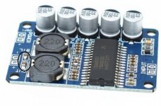
Its the first time I will mod a class D amplifier. I am thinking of replacing the input and output ceramic capacitors with foil ones. But with smd applied its difficult to recognize what exactly these ceramic capacitors are. I think the output capacitors are the ones I marked in the picture. Can you please help me what these capacitors are on the board and which values I should use?
Besides I am thinking of synchronizing the clock of the chips, but with the datasheet of the chip this is pretty clear.
Attachments
I don't know that board, but if the inductors are 22uH then its likely the caps follow the datasheet for that inductor. Perhaps your board deviates from that - hopefully someone with that board can answer definitively. What does the datasheet say for a 22uH? What impedance are your speakers? Class D output filters can be optimised for a known impedance.
I've done some more testing on mine. I tried a third smps 14.4v supply and it worked the same as the first 12V one. It seems the amp just didn't like the second one. Then I tried a 13.8V Sigma11 and the amp shut itself down. Both work apart but refuse to work together. Odd. Then I tried a 14V LT1083 and it gave the best performance so far. Great sound and a very dark background with no whine detectable at all. Its all kinda ironic - the second psu that whines like a 3 yr old was why I made this amp for 12V. Now I've used all 16V caps and find myself needing a different psu capable of higher voltages. Oh well. I'm sticking with the caps so a 14V supply it is.
and I'm going to try a TDA7377 in the other project using the case as a heatsink.
I've done some more testing on mine. I tried a third smps 14.4v supply and it worked the same as the first 12V one. It seems the amp just didn't like the second one. Then I tried a 13.8V Sigma11 and the amp shut itself down. Both work apart but refuse to work together. Odd. Then I tried a 14V LT1083 and it gave the best performance so far. Great sound and a very dark background with no whine detectable at all. Its all kinda ironic - the second psu that whines like a 3 yr old was why I made this amp for 12V. Now I've used all 16V caps and find myself needing a different psu capable of higher voltages. Oh well. I'm sticking with the caps so a 14V supply it is.
An externally hosted image should be here but it was not working when we last tested it.
and I'm going to try a TDA7377 in the other project using the case as a heatsink.
Last edited:
I ordered some of these blue bords.
Its the first time I will mod a class D amplifier. I am thinking of replacing the input and output ceramic capacitors with foil ones. But with smd applied its difficult to recognize what exactly these ceramic capacitors are. I think the output capacitors are the ones I marked in the picture. Can you please help me what these capacitors are on the board and which values I should use?
Besides I am thinking of synchronizing the clock of the chips, but with the datasheet of the chip this is pretty clear.
The SMD capacitors you have marked are the output filter capacitors. With 22uH you use 680nF. You may use 15uH and 1uF instead (optimized for 6 Ohm).
On DIYBudgetAudio.com, in the article "TDA8932 based class D amplifier", you find an example of "mods" based on this board. The input coupling capacitors are replaced with foil capacitors, but you may need to cut a PCB track doing that.
Thanks for your replies. I found that example but the picture is not clear how the connections are made. Moreover the output smd capacitors still seem to be there, are the foil capacitors added additionally?The SMD capacitors you have marked are the output filter capacitors. With 22uH you use 680nF. You may use 15uH and 1uF instead (optimized for 6 Ohm).
On DIYBudgetAudio.com, in the article "TDA8932 based class D amplifier", you find an example of "mods" based on this board. The input coupling capacitors are replaced with foil capacitors, but you may need to cut a PCB track doing that.
The input coupling caps are to the right of the IC in the photo you posted. Definitely replace them with the best you consider reasonable for the project - they should be 1uF.
You circled the output caps (680nF?) and it's good to replace them too but it won't have as much of an obvious effect as the input caps.
You circled the output caps (680nF?) and it's good to replace them too but it won't have as much of an obvious effect as the input caps.
On DIYBudgetAudio.com, in the article "TDA8932 based class D amplifier", you find an example of "mods" based on this board. The input coupling capacitors are replaced with foil capacitors, but you may need to cut a PCB track doing that.
I'd not recommend such a mod. Based on my own experience with TDA8932, the input circuitry is highly susceptible to RF pick-up. The smaller surface area of SMT ceramics is an advantage, changing to (physically much larger) foil caps is going to make the amp much more susceptible to RF pick-up.
Would it be better to remove the smd input coupling caps on the +ve input, replace them with smd ferrites, and then add the coupling caps off-board? Obviously, not replacing the -ve input coupling caps with ferrites as this would short the DC on the input to ground and puff the magic dragon.
- Home
- Amplifiers
- Class D
- Fasten seat belts. TDA8932 pessimistic review.