I can understand why you say that. It's one of the few things Douglas Self seems to think could be real and is the reality of the LM1875.
One idea I like Arcam used for the A60 was to use a current source ( CCS ) with a simple resistor bias chain. The CCS could pick up the heat of the heat sink. It was spaced from the heatsink so as to have no direct contact, just enough to do good work. The amplifier was set up after 20 minutes warm up. The idea came from the Sinclair Z30.The Sinclair was and is an excellent design far too advanced for the transistors they could buy. They used devices not unlike BD135/6 as outputs which whilst fast were not very strong. All the same a design coming from nowhere that history forgets. A year before the Sinclair Neoteric was not very Neo at all, very Tobey Disdale. Same date as JLH. Very likely how Naim got interested.
That A60 CCS also makes other things happen.
Haha you don't need Douglas Self to say it could be real. If you ever played with germaniums (was it AD161/162??) with drivers that ... too warmly embraced each other, and neglected these thermals, it could go "poof". Back to the shop "mom, give me some money".
I think it was also said in some book or magazine I had back then to pay attention to run drivers on their separate h/sinks spaced apart from outputs.
I think it was also said in some book or magazine I had back then to pay attention to run drivers on their separate h/sinks spaced apart from outputs.
Hello,
Just bought a JLH kit (PNP sanken A1216 JLH1969 single-ended class A power amp kit 10W+10W L168-27 | eBay) from Ebay.
For power supply, a simple variant will work OK (rectifier bridge+30.000uF) or should I build the advanced one, with transistors and the rest?
Thanks!
Just bought a JLH kit (PNP sanken A1216 JLH1969 single-ended class A power amp kit 10W+10W L168-27 | eBay) from Ebay.
For power supply, a simple variant will work OK (rectifier bridge+30.000uF) or should I build the advanced one, with transistors and the rest?
Thanks!
Last edited:
Are those a good quality MJ802 for the high power (2005) version JLH
I have some 20 pairs of Onsemi MJ15003 together with the complementary MJ15004 (I can separate them) but also I can use them for a P-P amp in the future.")
My question does those trannies wort to invest or I should go with the existing ONsemi?
6PCS Transistor MOTOROLA/ON/ST TO-3 MJ802 MJ802G | eBay
I do not recognize these brand.
I can buy the cheaper ONsemi MJ802 but I am not sure if they are the real things. Made of Mexico some has the Motorola logo.
At these moment I do not want to place an order at a reputeble store.
Greetings
I have some 20 pairs of Onsemi MJ15003 together with the complementary MJ15004 (I can separate them) but also I can use them for a P-P amp in the future.
My question does those trannies wort to invest or I should go with the existing ONsemi?
6PCS Transistor MOTOROLA/ON/ST TO-3 MJ802 MJ802G | eBay
I do not recognize these brand.
I can buy the cheaper ONsemi MJ802 but I am not sure if they are the real things. Made of Mexico some has the Motorola logo.
At these moment I do not want to place an order at a reputeble store.
Greetings
Hello,
Just bought a JLH kit (PNP sanken A1216 JLH1969 single-ended class A power amp kit 10W+10W L168-27 | eBay) from Ebay.
For power supply, a simple variant will work OK (rectifier bridge+30.000uF) or should I build the advanced one, with transistors and the rest?
Thanks!
I think you should contact Prasi about the JUMA type of PS....
The JLH on paper can work with a simple PSU if large enough. I suspect a 22 000 uF with 0R22 3 watt resistor and 10 000 uF is ideal ( A Pi filter ). Preferably a 10 000 uF to each ampifier section with the 10 000 uF close to the 2N3055, 2 x 0R22 if so. If 1.2 amps you will drop about 0.27V. If a fault devellops the reading will change. This PSU is only for class A designs. Use soft recovery diodes if available. You would make a bridge if so. What they seem to be is a diode with a critical capacitance built in which seems far better than an added one, It's just the diode junction doing what it needs when reverse biased. Facts are hard to find on this. They should send less noise into the circuits. Mostly Audiophiles dislike snubbers unless very carefully calculated. 100R+10 nF on the AC terminals only might work, not a simple 10 nF as oftenshown. This often makes the real world problems worse. These snubbers seem to be aimed at AM radio's when fitted early in the days of EM regs.
http://uk.farnell.com/on-semiconduc...ecovery-8a/dp/9843949?st=soft recovery diodes
http://uk.farnell.com/on-semiconduc...ecovery-8a/dp/9843949?st=soft recovery diodes
Hello
Here is my first post.
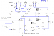
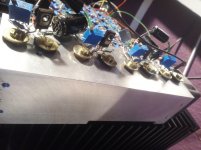
My name is Mike and I'd like to show You my version of JLH.
I wonder your opinion about this.
Regards. Mike
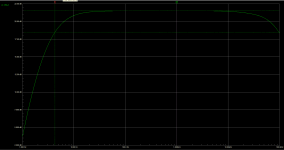
spec.
- Icc = 1.2A
- U = 28.6V
- bandwidth -3dB 4Hz to 95kHz.
Here is my first post.
My name is Mike and I'd like to show You my version of JLH.
I wonder your opinion about this.
Regards. Mike
spec.
- Icc = 1.2A
- U = 28.6V
- bandwidth -3dB 4Hz to 95kHz.
Attachments
Why did you not order from the same seller the PS he designed to these amps?
Assembled 2X10000uf Single rectifier PSU board for 1969 class A amp L168-26 | eBay
Assembled 2X10000uf Single rectifier PSU board for 1969 class A amp L168-26 | eBay
Are those a good quality MJ802 for the high power (2005) version JLH
I have some 20 pairs of Onsemi MJ15003 together with the complementary MJ15004 (I can separate them) but also I can use them for a P-P amp in the future.
My question does those trannies wort to invest or I should go with the existing ONsemi?
6PCS Transistor MOTOROLA/ON/ST TO-3 MJ802 MJ802G | eBay
I do not recognize these brand.
I can buy the cheaper ONsemi MJ802 but I am not sure if they are the real things. Made of Mexico some has the Motorola logo.
At these moment I do not want to place an order at a reputeble store.
Greetings
Hi Gaborela
There are some good tips on spotting counterfeit transistors on Rod Elliot's site.
Here is a link for you
Counterfeit Transistors
Regards
Mike
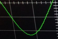
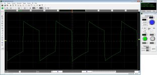
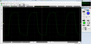
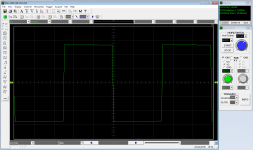
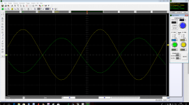
You need to determine whether all this 'noise' and 'hash' is a measurement artefact or whether its real. Until that is sorted out then I suspect you can not go any further.
The applied input voltage should look absolutely perfectly clean.
However, there appears to be quite a high level of quantisation noise on the digital scope trace.
Regards
Mike
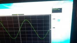
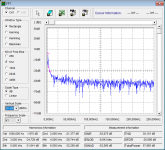
I did an FFT measurement and I am asking for help in the analysis.
Signal Up-p = 2.81V @1kHz
RE your schematic: are you really using a 5V or is it a 15V regulator?
And the diode in the bottom Darlington: is it a current-mirror or a thermal compensation (or a simple "give me a PN drop because of another BE junction in the Darlington")?
Hello,
Just bought a JLH kit (PNP sanken A1216 JLH1969 single-ended class A power amp kit 10W+10W L168-27 | eBay) from Ebay.
For power supply, a simple variant will work OK (rectifier bridge+30.000uF) or should I build the advanced one, with transistors and the rest?
Thanks!
Hi, could I suggest that you look at my post 4552 with a pointer regarding fake transistors. There is a link on that page regarding 2SA1216 transistors that may be of use to you.
Kind regards
Mike
RE your schematic: are you really using a 5V or is it a 15V regulator?
And the diode in the bottom Darlington: is it a current-mirror or a thermal compensation (or a simple "give me a PN drop because of another BE junction in the Darlington")?
there is a 5 volt regulator with 22V zener diode to ground. It give me a 27V stable voltage.
A diode on the bottom darlington works like a thermal compensation and drops 0.4 volt decrease Ube TIP141. It works good.
Thanks for the Powe Supply information!
I guess the transistors are fake if I look at the price - 45$ for stereo kit,
and if I look here,
2SA1216 SANKEN - Tranzistor: PNP | TME - Componente electronice
approx. 10$ 1pcs transistor..
I will weight them ( the fake ones are lighter, 15g, vs. 18g the original ones) and report back when the ebay kit arrives.
PS. I see 2SA1216 and other types in this EOL list, https://media.digikey.com/pdf/PCNs/Sanken/EOL_Notice_A_12_21_2017.pdf
Last edited:
I can't really see how you can make a distortion judgement based on the fact that the signals are so noisy.
Also, your screenshot of the scope shows 1.01v p/p and 17.5v p/p which I take to be input and output voltages. I can't reconcile those figures with the gain of the amp as configured in your circuit diagram. The gain is primarily set by R25 and R27, unless you are including a stage we can not see before the power amp.
Also, your screenshot of the scope shows 1.01v p/p and 17.5v p/p which I take to be input and output voltages. I can't reconcile those figures with the gain of the amp as configured in your circuit diagram. The gain is primarily set by R25 and R27, unless you are including a stage we can not see before the power amp.
- Home
- Amplifiers
- Solid State
- JLH 10 Watt class A amplifier