The JLH 2005: There are a lot of things, that prevent a inky, black, deep and depth sound - the most misunderstand as "bass". I would try a lot to get more focus, contour, less noise, less stress.
I would start with removing of C4, C5, C6, C7. And listen;-)
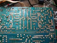
And with the new-solder, as shown below: The "solder-joints with the hole"-) Minimal diameter, minimal material;-!!! And listen;-)
You could continue, to better a little little bit, per cutting the holes;-) And listen;-)
All these works: the complete amp and all your sources. And so on;-)
And listen, listen, listen;-) Compare the amp with itself. The sources too - with itselfs. Not with others. That do much much later;-)))
I do not know your pcbs, but I am sure, there would be a lot to scratch and cut to better circuits and currents;-)-;
I would start with removing of C4, C5, C6, C7. And listen;-)
And with the new-solder, as shown below: The "solder-joints with the hole"-) Minimal diameter, minimal material;-!!! And listen;-)
You could continue, to better a little little bit, per cutting the holes;-) And listen;-)
All these works: the complete amp and all your sources. And so on;-)
And listen, listen, listen;-) Compare the amp with itself. The sources too - with itselfs. Not with others. That do much much later;-)))
I do not know your pcbs, but I am sure, there would be a lot to scratch and cut to better circuits and currents;-)-;
Attachments
Greeting Mr. Cumbb!
Thanks for the information you gave me, except for the tread immediately.
Unfortunately, at this time I do not have much time to devote to our amp, I have some family problems, but as soon as I am released I can swear that I will do these tests. More than anything else for curiosity and personal knowledge since I have never gone into such a push and detailed treatment of low-frequency circuits. In a remote past I did some experimentation in the UHF field where certain measures were essential for the correct functioning of the equipment and I thought they were totally unjustified in the BF sector ... I will try, I am curious to see the effect it does. In the meantime I can only thank, greet and I will certainly continue to read you.
Mleod
I can imagine that being in prison with probably no access to a soldering iron makes experimentation difficult. Still, as you say as soon as you are released you can address this.as soon as I am released I can swear that I will do these tests.
")
Erm...I wouln't take that term too specifically just yet, when a translation is likely involved. Often, English expressions are only clear within a context or an assumed context and that makes it difficult or embarrassing for others to use. Not that it's any of my business, Mleod may just be referring to meeting family responsibilities, as said...... as soon as you are released you can address this.
...
And with the new-solder, as shown below: The "solder-joints with the hole"-) Minimal diameter, minimal material;-!!! And listen;-)
You could continue, to better a little little bit, per cutting the holes;-) And listen;-)
All these works: the complete amp and all your sources. And so on;-)
And listen, listen, listen;-) Compare the amp with itself. The sources too - with itselfs. Not with others. That do much much later;-)))
I do not know your pcbs, but I am sure, there would be a lot to scratch and cut to better circuits and currents;-)-;
Concerns all in here;-)
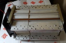
MEGA HEATSINK FOR MY HIGH POWER JLH
I won this mini heatsink on ebay for £50 a couple of weeks ago (without the fan).
It has 8 heatsinks isolated from one another and the frame with Tufnol spacers so I have mounted the 8, MJ802Gs without insulators with just a smear of heatsink paste. With fan its probably okay upto 500watts.
Quick question:
The dual psus using 18-0-18 v 220va transformers with 22mf per rail, are located in a separate box with umbilicals of about 1m long using XLR connectors. (otherwise the amp would be too heavy for me to lift)
In the amp case, there will be a further set of 47mfd caps per rail.
I may fit capacitance multipliers but does it matter whether they are in the psu box, or in the amplifier case?
Attachments
I may fit capacitance multipliers but does it matter whether they are in the psu box, or in the amplifier case?
Personally I took out my cap multipliers and replaced them with big caps (10000 uF in series with 0.15 Ohm in series with 22000 uF per rail per channel).
That learnt me how my amp sounded "shut in" with the cap multipliers. After reading some more up on those I suggest that you can put the multiplier anywhere you like as long as you put some serious caps close to the amplifier board (eg 10000 uF per rail per channel).
The only reason to fit cap multipliers is a cheaper method of hum reduction so they will be a last resort.
I don't think enough consideration is given to inserting active devices in series with the supply rails as they are effectively in series with the amp's output devices and of course, the load so its no surprise that they have an audible effect.
Right, more bits are in and it's going together. One problem I am having is with dry joints, or more specifically the solder not wetting out on the board. It's as if it's oily, but I have degreased it with meths. My soldering technique is OK (it certainly used to be back in the day) but I am finding the solder is going onto the lead but isn't wetting onto the board. It sits in a round bead on the lead instead. The solder is old stock Altai or similar, so it's good stuff. Am I missing something WRT board cleaning?
Sorry for the stupid question, I ought to be able to solder, and normally I can. I'm just not getting those nice tapered joints that I should.
Sorry for the stupid question, I ought to be able to solder, and normally I can. I'm just not getting those nice tapered joints that I should.
- Home
- Amplifiers
- Solid State
- JLH 10 Watt class A amplifier