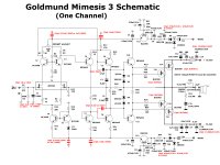
HOW TO INCREASE QUIESCENT CURRENT OUTPUT STAGE
Hi all, I built these 2 original boards with the attached schematic. The amplifiers are working but they show 2 problems:
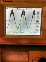
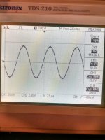
1. some high frequency oscillation shown just at the top of output sine wave at 1 KHz, 25 W RMS output over 8 Ohms resistive.
2. some visible crossover distortion.
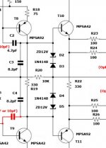
I used exactly the values shown at the schematic. The MOSFETs are BUZ901 and BUZ906 (not paired, just what it came in the box). I didn't populate the protection circuit components, just the amp.
Output offset voltage no load with shorted input is 2 mV adjusting R8.
The oscillation was reduced greatly by increasing gate resistors from 100 Ohms to 820 Ohms, but output power also decreased to a maximum of 95 W RMS with 56 V rails before clipping. The indicated optional capacitors are in place
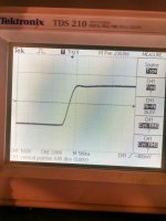
Raise time is 1us for the audio frequencies to 300 KHz and it responds flat.
I was about to measure quiescent current replacing the fuses with a 0.1 Ohm resistors and check voltage drop there. It seems that R22 330 Ohms could be adjusted to increase up to 180 mA (I guess this stage was designed for 100 mA or less)
I think that T5 is reversed, but I placed as the original schematic showed. Works fine for LTSpice simulation.
Could you please give me some help ?
Thank you !
Hi all, I built these 2 original boards with the attached schematic. The amplifiers are working but they show 2 problems:
1. some high frequency oscillation shown just at the top of output sine wave at 1 KHz, 25 W RMS output over 8 Ohms resistive.
2. some visible crossover distortion.
I used exactly the values shown at the schematic. The MOSFETs are BUZ901 and BUZ906 (not paired, just what it came in the box). I didn't populate the protection circuit components, just the amp.
Output offset voltage no load with shorted input is 2 mV adjusting R8.
The oscillation was reduced greatly by increasing gate resistors from 100 Ohms to 820 Ohms, but output power also decreased to a maximum of 95 W RMS with 56 V rails before clipping. The indicated optional capacitors are in place
Raise time is 1us for the audio frequencies to 300 KHz and it responds flat.
I was about to measure quiescent current replacing the fuses with a 0.1 Ohm resistors and check voltage drop there. It seems that R22 330 Ohms could be adjusted to increase up to 180 mA (I guess this stage was designed for 100 mA or less)
I think that T5 is reversed, but I placed as the original schematic showed. Works fine for LTSpice simulation.
Could you please give me some help ?
Thank you !
Attachments
Something does not look quite kosher with C2, C3, C4, and C5. In my opinion remove C3 and C4 and make C2 = C5 = 47pF. Gate stopping resistors can increase to 470 Ohms.
T5 is not reversed, it is just used in a weird way to fix the base voltage of the CCS.
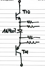
A simple close to optimum bias setting can be obtained by replacing R22 with a 1N4007 (almost any diode will do). Remove either rail fuse and connect your meter across the fuse socket to check for about 340 mA that would approximate 170 mA per output device which is close to optimal bias current for a lateral Mosfet.
T5 is not reversed, it is just used in a weird way to fix the base voltage of the CCS.
A simple close to optimum bias setting can be obtained by replacing R22 with a 1N4007 (almost any diode will do). Remove either rail fuse and connect your meter across the fuse socket to check for about 340 mA that would approximate 170 mA per output device which is close to optimal bias current for a lateral Mosfet.
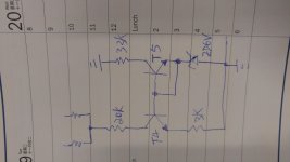
Nico is the attached drawing what you suggest ?
This change would increase the current to 340 mA ? How does this work ? I mean ... it will not be greater than that ?
I am concerned about ringing. Do you think that ringing is related to change the capacitors to 47 pF and remove the others ? Do I keep the 100 Ohms resistors or change to 470 ?
This change would increase the current to 340 mA ? How does this work ? I mean ... it will not be greater than that ?
I am concerned about ringing. Do you think that ringing is related to change the capacitors to 47 pF and remove the others ? Do I keep the 100 Ohms resistors or change to 470 ?
Attachments
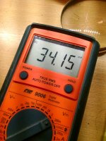
Nico, first I replaced one fuse with a 0.1 Ohm resistor and to my surprise the quiescent current was just ... 20 mA ! I left R2 330 Ohm as the original. Instead, I replaced R19 330 Ohm with a trimpot and adjusted to 435 Ohm and obtained 340 mA (170 mA each MOSFET current). No crossover distortion shown with 8 Ohm load.
Also replaced C2 and the other capacitor between collector and base of both T8 and T9 with 47 pF. The oscillation is still there and it occurs in the middle of the way applying input signal 1 KHz. No oscillation with small and large signals. The raise time is now worse, it increased from 1 us to 2.5 us.
Al these test with original 100 Ohm gate resistors.
Finally I guess if the 0.22 R30 resistor for the output coil should be 10 Ohms or so ...
No great improvements with the oscillation ...
Attachments
1. There is some thing wrong with that quiescent current. Your value is too low with Rbias as 330R. Please ensure quiescent current of LTP and VAS correct.
Please note that B-C of Q5 that is shorted. That make a CCS stable with any change of temperature. There is some discussion threads about constant current source on forum.
2. Keep compensation caps as original.
3. Gate resistors: The values of original that are quite low. L-MOSFETs easily oscilate with low value Rgate. Increasing Rgate value to 220R for P ch and 330R for N ch. and trying to adds few 100pF caps around G-D of MOSFETs.
Measuring again and if you still have osc. you need come back to (2) and proceeding modify values of compensation caps to values as red texts. My opinion is remove C3, C4. C2 increases to 22pF to 47pF. C5 keep as original.
Thank you Walkalone, I solved my problem today . The beauty of this (and other) amplifiers is minimalism. I tried to keep the schematic as Zen simple as possible. Glad to share this information  .
.
The first think I did was to place T5 correctly. Collector now goes north Col & Base shorted. Then I removed C1, C3 and C4 optional compensation caps. C2 and its symmetrical on T8 and T9 replaced by 10 pF ceramic discs. Greater values here destroy the frequency response, I tested 22pF and also 47 pF. Gate resistors replaced with 680 Ohms. R19 removed and replaced by a 1K trimpot adjusted to obtain 360 mA total quiescent current (180 mA for each MOSFET) after 30 minutes warm up, input shorted, no load connected. All the nasty oscillations and crossover distortion, gone.
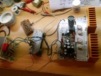
These 2 original project boards bought from Nagys, the member that once started this forum. He was right, he never lied, and he was nice to me sending me all kinds of good information. I kept this amplifier in a box with all its components obtained 3 years ago from Mouser and some other sources.
This is a silent, stable amplifier with an amazing response, 128W RMS sine before clipping over 8 Ohm. Responds from CC to 700 KHz flat. Raise time 500ns (square wave) I pushed the limit at 1 MHz full power (also flat !) and burned R31 because the Zobel network worked and a lot of energy was absorbed there. I changed the 0.22 Ohm resistor in parallel with the Zobel inductor with 10 Ohm.
This device works reallyHOT. I will work now in thermal contact between the signal transistors and drivers. I will probably fix some kind of heat sink there. T12 and T13 (I used TIP 35 and TIP36) are warm but need no heat sink IMO.
Kind regards
Roberto
I solved my problem today . The beauty of this (and other) amplifiers is minimalism. I tried to keep the schematic as Zen simple as possible. Glad to share this information .The first think I did was to place T5 correctly. Collector now goes north Col & Base shorted. Then I removed C1, C3 and C4 optional compensation caps. C2 and its symmetrical on T8 and T9 replaced by 10 pF ceramic discs. Greater values here destroy the frequency response, I tested 22pF and also 47 pF. Gate resistors replaced with 680 Ohms. R19 removed and replaced by a 1K trimpot adjusted to obtain 360 mA total quiescent current (180 mA for each MOSFET) after 30 minutes warm up, input shorted, no load connected. All the nasty oscillations and crossover distortion, gone.
These 2 original project boards bought from Nagys, the member that once started this forum. He was right, he never lied, and he was nice to me sending me all kinds of good information
. I kept this amplifier in a box with all its components obtained 3 years ago from Mouser and some other sources.This is a silent, stable amplifier with an amazing response, 128W RMS sine before clipping over 8 Ohm. Responds from CC to 700 KHz flat. Raise time 500ns (square wave) I pushed the limit at 1 MHz full power (also flat !) and burned R31 because the Zobel network worked and a lot of energy was absorbed there. I changed the 0.22 Ohm resistor in parallel with the Zobel inductor with 10 Ohm.
This device works really
HOT. I will work now in thermal contact between the signal transistors and drivers. I will probably fix some kind of heat sink there. T12 and T13 (I used TIP 35 and TIP36) are warm but need no heat sink IMO.Kind regards
Roberto
Attachments
Not only short Col and Base. Collector and emitter are reversed. Both transistors are drawn symmetrically.
I must say that the original circuit uses T5 inverted, and it works too. Also I simulated the stage with LTspice and there is no apparent functional diference.
I decided to use the standard schematic for a Wilson mirror. It works perfectly well this conventional way.
Kind regards
I must say that the original circuit uses T5 inverted, and it works too. Also I simulated the stage with LTspice and there is no apparent functional diference.
I decided to use the standard schematic for a Wilson mirror. It works perfectly well this conventional way.
Kind regards
Thank you Walkalone,
The first think I did was to place T5 correctly. Collector now goes north Col & Base shorted. Then I removed C1, C3 and C4 optional compensation caps. C2 and its symmetrical on T8 and T9 replaced by 10 pF ceramic discs. Greater values here destroy the frequency response, I tested 22pF and also 47 pF. Gate resistors replaced with 680 Ohms. R19 removed and replaced by a 1K trimpot adjusted to obtain 360 mA total quiescent current (180 mA for each MOSFET) after 30 minutes warm up, input shorted, no load connected. All the nasty oscillations and crossover distortion, gone.
These 2 original project boards bought from Nagys, the member that once started this forum. He was right, he never lied, and he was nice to me sending me all kinds of good information
This is a silent, stable amplifier with an amazing response, 128W RMS sine before clipping over 8 Ohm. Responds from CC to 700 KHz flat. Raise time 500ns (square wave) I pushed the limit at 1 MHz full power (also flat !) and burned R31 because the Zobel network worked and a lot of energy was absorbed there. I changed the 0.22 Ohm resistor in parallel with the Zobel inductor with 10 Ohm.
This device works really
Roberto,
I wanted to send a PM to you. Can you tell me how to do it?
I defer to other's experience when it comes to matching requirements. But, profusion does have color coded Latfets and suggests that matched sets do not need source resistors. A group buy could perhaps produce plenty of matched sets:
https://www.profusionplc.com/pdf/selected-mosfets.pdf
All of the Exicon MOSFETs have better power ratings than the 1058/J162 in the schematic. So really it's a question of what you want. Even with the weakest 125W Exicons, the best DIYaudio heatsink is half of the power limitation. Use the stronger 250W Exicons and you only gain 25% more power margin. So really it just depends on what you are willing to pay for.
So we could use a single pair of big Exicons capable of 556w and assume 60% efficiency, I can get a 335w amp if I could provide adequate cooling. Say a CPU cooler with heat pipes and a fan? Then no matching needed. No ballast resistor either.
On my Class A amp designed by Aksa, I run 165w dissipation on a single IXYS using CPU cooler worh heat pipes with a ceramic spacer and thermal grease and a fan. It’s rated for 600w, so still way below its envelope. I know it’s capable of more because I accidentally ran it for 24hrs with the fan switched off. It did not let out the magic smoke.
On my Class A amp designed by Aksa, I run 165w dissipation on a single IXYS using CPU cooler worh heat pipes with a ceramic spacer and thermal grease and a fan. It’s rated for 600w, so still way below its envelope. I know it’s capable of more because I accidentally ran it for 24hrs with the fan switched off. It did not let out the magic smoke.
Nelson Pass had some specific criteria on how to derate amps to be reliable, as any single failed amp is an enormous cost for the company. I wish I could find that info.
But I would add some hefty margin in there. The amp may survive Tj=150C at full power, but the thermal cycling still reduces reliability. Caps getting hot will not last as long. Furthermore, I worry the heatpipes will increase the heat stress on the chips by causing uneven temperature.
Of course, people rarely use amps at their full power if they care about sound quality, so you see a lot of people here getting by with anemic heatsinking.
- Home
- Amplifiers
- Solid State
- Goldmund Mods, Improvements, Stability