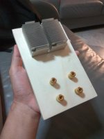
The heat spreader need only be 6 mm thick and a little wider than the MT200 transistors, at about 25 mm minimum. The slot on my Caowei board is only 29.5 mm, so there is not enough room for the next standard 30 or 31.7 mm wide section. Perhaps your board slot is a little wider.
I would avoid that thick section from Taobao - too thick and too much hassle. Surely there are 25 x 5-7mm sections in the scrap bin of an aluminium reseller somewhere. You have time on your side if you take it gently with power, so keep looking occasionally. The extra height to accommodate that extrusion wouldn't be a problem for heat but you'd probably need to adjust the Vbe multiplier transistor lengths to keep them in close proximity to the case for best stability and reconsider power transistor lead lengths too.
I bought the aluminium for mine in a 2m offcut length but it wasn't that expensive and I have already used the rest on other projects.
Thanks for the advice ian, I've called up a local aluminum supplier and turns out they're only about 10-12km from my place. They said I need to buy a minimum of 6 meters but they can cut it to length at the shop. I figure once I go there I can still haggle a bit and not need to buy 6 meters. Sensible 2m could do I think.
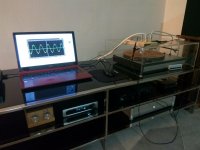
Anyway, I made a dummy load the past day and today managed to hook it up to the amp and my USB scope.
When I turn up the preamp volume the amp starts to make a ringing sound. I wouldn't say its a humming sound because its rather high pitched. Here's a google drive link for the recording.
ringing sound.mp3 - Google Drive
It gets loud around 14 seconds in. I recorded using my phone beside the amp. It starts to sound at around 12 o'clock on the preamp for sine wave, 1-2 o'clock for triangle waves, and much earlier at 8-9 o'clock for square and saw tooth waves. Maybe something about the sharp rise and fall of the waves? Since square waves and saw tooth have very steep rise and fall.
But other than that the amp sounds fantastic.
Last edited:
The last time I heard a high pitched squeal from an amp it was oscillating at several 10s of MHz. The power transistors made the noise. But if your scope doesn't show anything...
What's the bandwidth of your scope?
Is the squeal the same frequency as the test tone? If so it may be ok if it is just due to very high currents. The 14s delay is curious - sounds like a thermal timescale. What's your dummy load? Are you sure it isn't the load that is squealing?
What's the bandwidth of your scope?
Is the squeal the same frequency as the test tone? If so it may be ok if it is just due to very high currents. The 14s delay is curious - sounds like a thermal timescale. What's your dummy load? Are you sure it isn't the load that is squealing?
Last edited:
When I turn up the preamp volume the amp starts to make a ringing sound. I wouldn't say its a humming sound because its rather high pitched.
You may have oscillation in the signal path, but then you should see something on the scope, especially if you hear it.
What was the test frequency?
I've heard similar sound from several E-type power transformers. Usually happens at 10-12kHz test tone and disappears above or below that frequency. I couldn't remove it no matter what I tried. I guess some sort of excitation of mechanical resonance. No idea why though.
Do you have an EMI filter at the AC input?
Member
Joined 2009
Paid Member
I've had this parasitic noise thing before too. I cant remember the details, I also didn't see anything on the scope and I believe I had a resistive load. I wondered if it was a capacitor or two at the time but more likely to be a coil. Perhaps it was the load, couldve been a wire wound resistor. I remember the pitch of the sound changing with the pitch of the test signal. I never found it to be a problem with the finished amp.
Last edited:
1) My scope is the fairly basic Hantek 6022BE. It has a bandwidth of 20MHz. Nothing shows on my screen except for the test signal.The last time I heard a high pitched squeal from an amp it was oscillating at several 10s of MHz. The power transistors made the noise. But if your scope doesn't show anything...
1) What's the bandwidth of your scope?
2) Is the squeal the same frequency as the test tone? If so it may be ok if it is just due to very high currents. 3) The 14s delay is curious - sounds like a thermal timescale. 4) What's your dummy load? Are you sure it isn't the load that is squealing?
One problem with it is my laptop has a bad battery and power adapter. Without connecting it to another device with earthing like my USB DAC with the 3 prong power jack, you can feel some current leakage on the laptop body. So some current could be affecting the scope reading and you can see grunge on the scope trace starting from 1V below.
2) Yeah now that you mentioned it, it does sound like its the same frequency. I ran a frequency sweep and the ringing corresponds to the frequency sweep.
3) The 14s delay is there because the volume was lower in the first 14 seconds. The ringing sound gets louder and stops at that volume.
4) My dummy load is a pair of 8ohm 50W resistors mounted on a CPU heatsink. The load isn't making noise, I placed it on top of the rack while the amp is at the bottom tier.
I'm gonna need to get a higher rating load resistor or at least bigger heatsink with fan because I've just tested it out again and the heatsink got hot. Also I know I've mentioned it a few times the amp case feels only warm to the touch? I lifted it up a bit and touched the bottom case at the output transistors and it was very hot. However with the whole aluminum case thing going on, I turned it off for like a few minutes and the temperature dropped very quickly. As usual Ian is right, I'm gonna need the spreader bar if I want to run it loud.
1) See above1) You may have oscillation in the signal path, but then you should see something on the scope, especially if you hear it.
What was the test frequency?
I've heard similar sound from several E-type power transformers. 2) Usually happens at 10-12kHz test tone and disappears above or below that frequency. I couldn't remove it no matter what I tried. I guess some sort of excitation of mechanical resonance. No idea why though.
3) Do you have an EMI filter at the AC input?
2) Yeah when I ran that frequency sweep it appeared within a small window of frequency. With the volume at 12 o'clock it only sounded between 3~7kHz. It could very well still be making the sound lower and higher than that but just out of my range of hearing.
3)No. And by EMI filter do you mean something like a ferrite ring kind of filter?
Yea the amp and everything sounds fine, it only has that slight ringing that corresponds to the test signal pitch. Like the kind of sound when you enter a CCTV shop or other electronic store.I've had this parasitic noise thing before too. I cant remember the details, I also didn't see anything on the scope and I believe I had a resistive load. I wondered if it was a capacitor or two at the time but more likely to be a coil. Perhaps it was the load, couldve been a wire wound resistor. I remember the pitch of the sound changing with the pitch of the test signal. I never found it to be a problem with the finished amp.
So for those who are interested, here's some square and sine waves I got. It looks pretty grungy but I believe that's the laptop USB contaminating. It looks like that with no inputs and from its own square wave generator as you can see from the last image.
Imgur: The most awesome images on the Internet
Input was from Matrix Mini-i DAC, signals were generated from Online Tone Generator - Free, Simple and Easy to Use.
Attachments
Your 20 MHz bandwidth 'scope should detect amplifier oscillation from most bipolar transistor deigns, since it will likely not be much higher than 400 kHz but I would not depend on that. Zoom in on the trace by using a shorter (X) scale period and see if the trace appears thick and so check that there is not much more going on than a simple sinewave.
Your dummy load sure hasn't got enough heatsinking for more than a very short period. Without the designated fan and ducting for those CPU coolers, the efficiency will be very low - as in useless. You don't seem to have mounted the resistors yet so use a good quality heatsink compound, to get optimum thermal transfer. With a dummy load, an insulating type is not essential and conductive, silver bearing types will be OK, as long as you can still fasten the resistor down absolutely flat on the sink over its full contact area. Arcol resistors should be fine for insulation from the outer metal cladding. Otherwise, check that they really are still isolated from the heatsink when mounted, only because I once found a couple of cheapo, unbranded types that were not.
If you think about it, each amplifier in the NAP200 is good for 100W/4 ohms and your heatsink would need to be rated at 0.3°C/W to keep that amount of dissipation below finger-scorching temperature. That's a pretty big and expensive heatsink for DIYs to buy so a properly fitted fan forced sink is a fair option. I happened to find a short length of heavy, industrial heatsink extrusion which I measured at ~0.2°C/W for my dummy load and that takes quite a few minutes to get hot with almost 200W disspation from 2 X 100W metalclad resistors, similar type to yours.
Hi!
Considering the sweet NAP 200 dr AMP build. How is the cone handling in this model? You are in for a Damping Factor of 15. 15! This is some what concerning and you don't want your 10" cones end up in long resonances.
https://www.naimaudio.com/sites/default/files/Naim NAP 200 DR HFW_Mar16.pdf
Any thoughts?
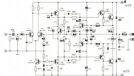
Trying to fire up a clone board
This thread is amazing for the amount of depth of knowledge that has been shared. Hopefully someone will be able to nudge me in the right direction.
I have a pair of NAP140 clone boards that I have just assembled (appear to be closer to the NAP250 schematic though).
I have tried to carry out the initial setup with the power trannies removed and using a 32v Lab supply, but I can't get it working.
I am getting in the region of 1.2v across R12 & R13. Variable resistor has no effect.
Setup: Using a basic lab supply, I have V+ connected to +32V, V- connected to 0v. This PSU has current limiting and soft start.
Am I supposed to connect the Input GND and Output GND together at this time?
Am I correct in thinking that these GND points are not to be connected to V-?
A few measurements (wrt 0v):
TR4: VE=32, VB=32, VC=0.7
TR1: VC=32v, VE=1.5, VB=0.5
TR3: VC=1.3, VB=0.5, VE=0
TR5: VC=0.7, VB=0.7, VE=0.7
TR11: VC=32, VB=1.9, VE=1.9
I have checked all the transistors are correctly oriented per the schematic. They all appear to diode check fine too.
Hoping I'm doing something obviously silly that someone can point out!
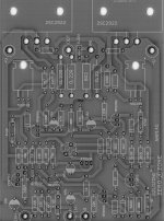
Here is the PCB and the schematic that matches the closest.
Thanks and Merry Christmas!!!
This thread is amazing for the amount of depth of knowledge that has been shared. Hopefully someone will be able to nudge me in the right direction.
I have a pair of NAP140 clone boards that I have just assembled (appear to be closer to the NAP250 schematic though).
I have tried to carry out the initial setup with the power trannies removed and using a 32v Lab supply, but I can't get it working.
I am getting in the region of 1.2v across R12 & R13. Variable resistor has no effect.
Setup: Using a basic lab supply, I have V+ connected to +32V, V- connected to 0v. This PSU has current limiting and soft start.
Am I supposed to connect the Input GND and Output GND together at this time?
Am I correct in thinking that these GND points are not to be connected to V-?
A few measurements (wrt 0v):
TR4: VE=32, VB=32, VC=0.7
TR1: VC=32v, VE=1.5, VB=0.5
TR3: VC=1.3, VB=0.5, VE=0
TR5: VC=0.7, VB=0.7, VE=0.7
TR11: VC=32, VB=1.9, VE=1.9
I have checked all the transistors are correctly oriented per the schematic. They all appear to diode check fine too.
Hoping I'm doing something obviously silly that someone can point out!
Here is the PCB and the schematic that matches the closest.
An externally hosted image should be here but it was not working when we last tested it.
An externally hosted image should be here but it was not working when we last tested it.
Thanks and Merry Christmas!!!
Setup: Using a basic lab supply, I have V+ connected to +32V, V- connected to 0v.
You need symmetrical PSU (like +32V, 0V, and -32V) to properly turn the amp on.
Thanks but I think the NAP boards are supposed to run on 30-40VDC. (The schematic is a bit misleading and marked 40v top and bottom).
If I put 64VDC on the rails (+32V : -32V), I think I might let the smoke out..I read posts by another person who smoked their boards with 44VDC.
Most builders have used an AC transformer then bridge rectified to around 40ish VDC, but I've heard others mention that they used a lab supply also.
I figured DC at the rails is DC whether it comes from a transformer or a lab supply (for initial test purposes anyway).
The supply voltages necessary for the original NAP series amplifiers varies from +34/0/-34VDC to +40/0/-40VDC. The limitation with the larger models is mainly due to voltage ratings of the VAS transistors, TR4 and TR6 as shown on your post of Neil McBride's schematic. These are important for Naim type sound quality. Though there's very little difference between the models, that is actually the common, generic NAP design with components as per the early NAP250 design, which used fully regulated supplies of +/- 40V to enable the max. power rating of 125W/channel /4 ohms.
I doubt your build will be using the original (genuine) transistors marked on the schematic - maybe not the same as marked on the PCB either, so check any substitutes and odd-looking brand marks out thoroughly - even those with the same part numbers can have different pinouts from different manufacturers and this spells big trouble.
Most people having difficulty getting their kits to work, come unstuck by using substitute small signal transistors which often have different pinouts to the board layout. In the past, that was caused by the kit suppliers' choice of substitutes with no information or explanation. Now, newcomers to DIY also mess about with their own ideas of what they think are better parts right from the outset and of course, voltages go haywire and often burn with the wrong pinout or wrongly fitted parts.
BTW - The power supply must be connected with the common 0V to ground if you expect it to work properly. The 0V connection is to the input ground symbol shown at lower left side of the schematic. PCBs sometimes have 2 holes there, one for signal ground and the other is linked to the PSU star earth. I suspect the external PS will prove noisy (a hum) using a direct connection without a proper chassis and star earthing (which can be followed from the details of setting up Avondale Audio's NCC200 modules - Google it.
Thanks
Thanks for all the replies and in particular Ian for your detailed response.
The schematic makes much more sense now with +40 and -40, apologies for not taking the earlier hints.
The components I have all match the PCB and diode check as expected. The last 4 transistors in the system were (surprisingly) matched pairs.
Just another question, what size transformer would you suggest? Would 200VA be sufficient to cover 70w*2 or would it be better (safer) to run a higher margin such as 300VA?
- Home
- Amplifiers
- Solid State
- NAP-140 Clone Amp Kit on eBay