For fine pitch micro USB pins, liquid flux with a flat iron tip was a game-changer. As in no sweat. ") Now I have a set of completed cap MX and load sharing boards. Just have to cut my first traces and figure out how to wire them to the PCA board. Will I need to drill holes for the wire after the trace is cut, or can I just expose some copper trace on each side of the removed portion and surface mount the wires to that?
Now I have a set of completed cap MX and load sharing boards. Just have to cut my first traces and figure out how to wire them to the PCA board. Will I need to drill holes for the wire after the trace is cut, or can I just expose some copper trace on each side of the removed portion and surface mount the wires to that?
Now I have a set of completed cap MX and load sharing boards. Just have to cut my first traces and figure out how to wire them to the PCA board. Will I need to drill holes for the wire after the trace is cut, or can I just expose some copper trace on each side of the removed portion and surface mount the wires to that?Attachments

Nice work there StellarE! Is that load sharing board to allow two batteries or to allow seamless charging vs battery power? That’s neat work.
For cutting the trace just expose bare copper by scraping off mask and solder directly to it. No holes needed as you can’t drill there because of stuff on other side.
For cutting the trace just expose bare copper by scraping off mask and solder directly to it. No holes needed as you can’t drill there because of stuff on other side.
Raptor's board allows both battery charging via USB and direct USB power. I have one of those tablet batteries and a little eBay voltage step-up that I'll cram in the tin too. I also bought parts for CRCRCRC but I will probably only try adding that if I can hear noise from USB power.
I am also looking forward to seeing how MoFo inductor idea works out in this amp. Sounds like a great addition for a desktop build.
I am also looking forward to seeing how MoFo inductor idea works out in this amp. Sounds like a great addition for a desktop build.
Last edited:
YOB, did you manage to wire in the CapMX without cutting a trace? Looking at this photo of your work. Looks like you are going between a connector header hole and a pin from the switch in the pot? Seems easier!
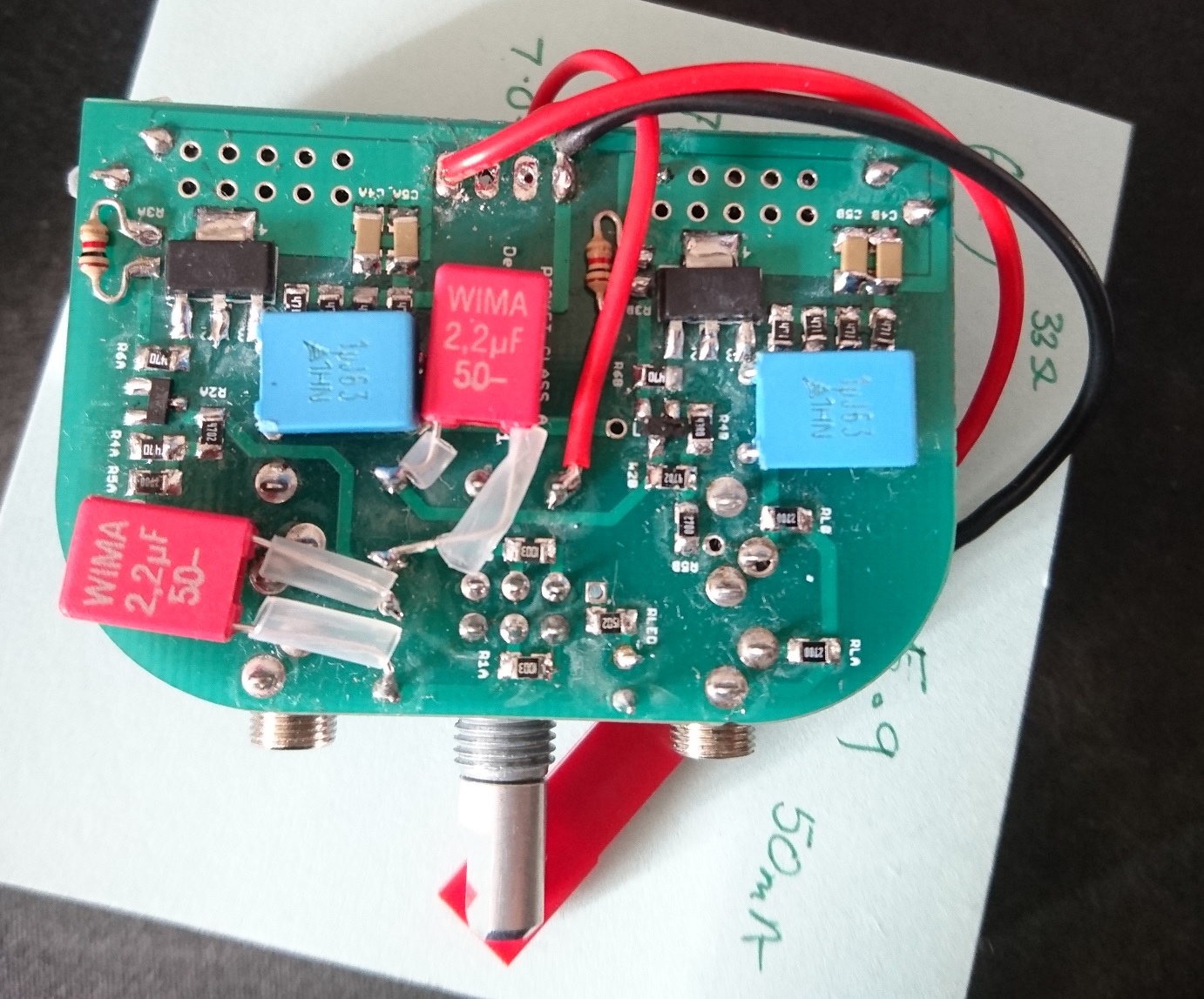
Below is how Raptor suggested connecting it in post 1178 (red lines are cuts). He also said that he had to remove the header for some reason. Is that really necessary?

Maybe adding the additional boards require the more difficult hookup? Sorry I have to lean on you all here but as you know my grasp of circuitry is zilch. I don't want to screw anything up...
Below is how Raptor suggested connecting it in post 1178 (red lines are cuts). He also said that he had to remove the header for some reason. Is that really necessary?
Maybe adding the additional boards require the more difficult hookup? Sorry I have to lean on you all here but as you know my grasp of circuitry is zilch. I don't want to screw anything up...
Attachments

Last edited:
...Sorry I have to lean on you all here but as you know my grasp of circuitry is zilch. I don't want to screw anything up...
As i see it and hopefully xrk971 and others will agree you will like to keep everything bonded as small and short as possible, when executed this way don't worry anymore because you can't do any better because of real world physical sizes and practical ways to mount stuff relative to schematic. A note for explanation is bigger physical sizes of components and wires means higher RLC interference values and is why small modern SMD tech can improve performance compared to bigger and bigger sizes as we look into the past, so in xrk971 used SMD sizes for this build he not only made it possible to squeeze hole complete amp into a relative small tin box, he also gets higher performance in less RLC interference compared to using old tech sizes.
Last edited:
Is there a through hole equivalent to the BF862-215?
The unobtanium 2sk170 is close and allows higher voltage, but BF862 is ultimately a better performer for lowest noise. So no, not really. The BF862 is now also end of life so in a few years will have a similar status as 2sk170. There is the LSK170 that could work still.
@StellarE:
Byrtt is right. Just keep the leads as short as possible. Although if inside the metal tin, it’s a pretty effective RF shield.
Last edited:
As i see it and hopefully xrk971 and others will agree you will like to keep everything bonded as small and short as possible, when executed this way don't worry anymore because you can't do any better because of real world physical sizes and practical ways to mount stuff relative to schematic.
Thanks, Byrtt. So you are saying that splicing my boards in either way will work fine? But Raptor's way is technically preferable because it keeps the wires shorter?
Even though Raptor described his mod's hookup scenario in words, I am a visual learner to the max and with three new boards to add, I think I am going to have to draw a picture showing all the new lead pathways and post it here for confirmation. So glad to have you all as a learning resource.
Merry Christmas everyone
Last edited:
Thanks, Byrtt. So you are saying that splicing my boards in either way will work fine? But Raptor's way is technically preferable because it keeps the wires shorter?
Even though Raptor described his mod's hookup scenario in words, I am a visual learner to the max and with three new boards to add, I think I am going to have to draw a picture showing all the new lead pathways and post it here for confirmation. So glad to have you all as a learning resource.
Merry Christmas everyone
Thanks wishes for Christmas and same to you and family : ) think my note was that you in general can have some piece in mind because biggest area of tin box is so small by itself that when compared to old tech your mods will always be relative short distances meaning less parasitic RLC interference.
Admit haven't set me into your particular schematic task but here a few hints that maybe can help a bit to visualize your task:
If you want documentation measure PCA electric performance with soundcard and REW before doing any modifications, then one can quality compare results after mod that data is still up to original or better or if it happen go worse direction will probably need more attention.
For lay out try think about any distance other than absolute zero which is impossible in real world (R=low/zero impedance, L=low/zero inductance C=low/zero capacitance) will add some more or less parasitic RLC interference values. Best isolator is air all other materials such as PCB and wire isolation will add parasitic capacitance (C). Long non paired and non twisted wires will increase loop area and raise parasitic inductance (L) plus add more resistance (R). Electric circuits often have both DC and AC potentials to care about the higher AC frq bandwidth is the higher speed circuit is able to be in control of and not distort output verse input signal and here parasitic RLC interference is often the culprit in that parasitic capacitance (C) makes AC signal short out at high frq (AC low pass filter) and parasitic inductance (L) also low pass AC signal in it increase AC impedance at higher frq so circuit is not in good control and speed up there. When we take decisions for physical layout it can often be good idea think a bit visual as we ourselves are the electron going down that layout and frequency wise if AC signal meet more routes it will always pick the lowest impedance road, that's also how filtering works using RLC components by purpose.
Where one physical tap wires including ground points can mean a lot for circuit performance, for example a speaker return or head phone ground return wire is a dirty high current return wire and should be bonded physical more upstream closer to power supply ground than input ground is tapped because those dirty current fluctuations will ruin sensitive input get a stiff staple reference point. In visual manner electric layouts can often be compared to water pipes and their flow performance, for example if one wants a steady flow/pressure water tap we don't hack it into existing serial net of often used pipes and other taps because their use will ruin this new tap having a steady flow/pressure, instead for task we probably build a new longer parallel pipe all the way back to main supply.
Right its looks be pure DC supply portion part and PCB also include reasonable high value capacitive buffer, but think the way power pull will be from DC supply is AC switching dictated as input audio signal demands power from DC supply.
Then again complete unit is so small so probably no problems at all for this build making it a good stiff low impedance supply
Then again complete unit is so small so probably no problems at all for this build making it a good stiff low impedance supply
Last edited:
Hi,
Just trying to find my way around the design and this large thread.
On the opening post there is this line -
If I click on it, it just opened a blank page ?
Just trying to find my way around the design and this large thread.
On the opening post there is this line -
Edit (Dec 22, 2017) - here is the latest BOM that I use for low impedance cans with a smooth sound signature.
If I click on it, it just opened a blank page ?
Hi,
Just trying to find my way around the design and this large thread.
On the opening post there is this line -
If I click on it, it just opened a blank page ?
Sorry about that bad link.
Should be this:
http://www.diyaudio.com/forums/group-buys/302859-xrk971-pocket-class-headamp-gb-140.html#post5284641
Let me fix index. Thanks.
X
Probably not a good idea, but would it be possible to substitute R5 and RL 270 Ohm with either 200 or 330 Ohm? For some reason I'd like to use the following 'audio' resistors :
Mouser No: 754-RS2012P-331-DT53
Mfr. No: RS2012P-331-D-T5-3
Mfr.: Susumu
Otherwise I'll just use 270 Ohm from a different series.
:Mouser No: 754-RS2012P-331-DT53
Mfr. No: RS2012P-331-D-T5-3
Mfr.: Susumu
Otherwise I'll just use 270 Ohm from a different series.
Probably not a good idea, but would it be possible to substitute R5 and RL 270 Ohm with either 200 or 330 Ohm? For some reason I'd like to use the following 'audio' resistors
Mouser No: 754-RS2012P-331-DT53
Mfr. No: RS2012P-331-D-T5-3
Mfr.: Susumu
Otherwise I'll just use 270 Ohm from a different series.
Make R5=200ohm and RL=330ohm and it should work fine. Nice performance actually. This is pushing 1.2vpp into 330ohms with 58mA bias current from 16.4v supply.
Harmonic Frequency Fourier Normalized Phase Normalized
Number [Hz] Component Component [degree] Phase [deg]
1 1.000e+03 9.126e-01 1.000e+00 -179.97° 0.00°
2 2.000e+03 2.724e-04 2.985e-04 90.14° 270.10°
3 3.000e+03 5.728e-05 6.276e-05 -179.89° 0.08°
4 4.000e+03 1.017e-06 1.114e-06 -102.06° 77.90°
5 5.000e+03 5.473e-08 5.997e-08 179.87° 359.84°
6 6.000e+03 1.409e-07 1.544e-07 179.51° 359.48°
7 7.000e+03 1.214e-07 1.330e-07 179.98° 359.95°
8 8.000e+03 1.062e-07 1.164e-07 179.98° 359.95°
9 9.000e+03 9.469e-08 1.038e-07 179.99° 359.95°
Total Harmonic Distortion: 0.030507%(0.030480%)
Attachments

Last edited:
According to StellearElephant, who did listening tests (all subjective), if I can paraphrase him, KA sounds more detailed and has good bass and balanced . Silmic II is smoother and less forward and softer details. It’s all a matter of taste. He also found that adding film bypass did not change much.
I've been trying to find a 6mm d-shaft max. 12mm knob, however they seem to be difficult to come by. Any idea as where to get one?
Also is it ok to use 10K or 15K for RLED (instead of 12K)?
Work fine aluminum alloy knob 15MM * 16.5MM 15MM * 17MM silver half shaft hole D hole potentiometer-in Switch Caps from Home Improvement on Aliexpress.com | Alibaba Group
Also is it ok to use 10K or 15K for RLED (instead of 12K)?
Always go for the larger 15k resistance which means the led will be dimmer.
Generally you find such indicator leds annoying if they are too bright
Cannot be more precise since we do not know the exact parameters of the led you purchase, they all vary slightly.
- Home
- Group Buys
- xrk971 Pocket Class A Headamp GB