Hi Edmond,
I'll DL the new and give it a try.
I wrote apps in C for MSdos, skipped C++ entirely went to Dalphi for win apps and now dotnet using C#. I got turned off from what looked like 1000 lines of code just to get a win form up.
I've never created a win32 app using C so I don't know about accessing the win api's with c.
.However in most other languages a closing event would be registered. The X button or other would call or trigger the closing event and in the even callback the Dispose() function/method would be invoked.
This seems to be standard.
By the way my hat is off to you for sticking out with C. Seems like doing it the hard way. This app is fast, graceful and nicely presented aside from the enormous technical effort. A lot of thought has gone into this.
Excellent job all around.
Cheers,
Hi David,
First, thank you for your kind words.
Regarding the exit procedure, in the past I did it the standard way. Later on I tried a non standard brute force method. Why, I can't remember precisely. Today I reverted back to the standard method. As for version 1.46.6, it's almost standard. In the meantime, I've uploaded an even more standard version: 1.46.7. Please use this one. In case the app still doesn't close correctly, please don't hesitate to contact me.
Good luck.
Cheers, E.
Hi Edmond,
As pointed out by other members some pf the messaging is bit confusing.
When I enter a frequency I get the message "Warning sample rate is whole multiple of frequency" It leaves me guessing at what this means. I think what your saying here is the frequency must be a whole multiple of the sample rate.
It would better for the user if the messages where more direct. Like "Frequency must be a whole multiple of sample rate" or something like that.
Would it be correct to guess that the intent here is that the generator frequencies be coherent with the bin frequencies?
I might suggest perhaps having a drop down list of frequencies the user can choose from that satisfy the requirement. Or a routine that snaps the users input frequency to the nearest frequency that meets the requirement.
Cheers,
Great!@Edmond
It's seem to be closing fine now. It disappears form the process list in task manager.
Hope it works with the RTX. In case of issues, please let me know.Hi Edmond,
Very interesting and nicely done package. Congrats!. Thanks for making it available.
Hope to try it out with my RTX tonight.
Cheers, E.
It does work with my RTX, no error messages.
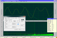
I'm still confused about the calibration though. I choose 0dBV out and 0dBV in at the RTX, and my DMM has confirmed that at this setting 0dBFS equals 1Vrms, so I set "Calibration ADC-1/2" to 1.414 (as shown in the screen capture).
However, under this setting, I'll have to set "Output level (Vp)" under Preference->Distortion to be less than 0.707, or else the input becomes over range and end up with very high distortion.
Attachments
Anatech is also asking about the 1.414Vpk reading in the RTX thread.....................
I'm still confused about the calibration though. I choose 0dBV out and 0dBV in at the RTX, and my DMM has confirmed that at this setting 0dBFS equals 1Vrms, so I set "Calibration ADC-1/2" to 1.414 (as shown in the screen capture).
However, under this setting, I'll have to set "Output level (Vp)" under Preference->Distortion to be less than 0.707, or else the input becomes over range and end up with very high distortion.
Is this the same as here?
I found the reply to Anatech confusing.
Microsoft Security Essentials says the zip contains a virus and automatically deletes the file. This is a first for me. Safe or no?
BK
Downloaded again today (12/10) and renamed the unzipped file per the readme. No false positives or complaining by MSE.
Is there a summary of DiAna settings appropriate for the RTX?
BK
yes one is using arta and this using Diana.That question in the RTX thread was about ARTA, and this thread is about a totally different software (DiAna) that is still under development.
While both questions are about calibration, it’s a very different matter.
Both are using RTX and both have a reading of 1.4V and both are confused.
So am I.
So I asked.
I'm glad to hear that.Downloaded again today (12/10) and renamed the unzipped file per the readme. No false positives or complaining by MSE.
The setting only depends on your needs, of course.Is there a summary of DiAna settings appropriate for the RTX?
BK
I don't have an RTX, but I can't imagine there are settings in particular appropriate for the RTX.
Cheers, E.
Calibration
Tell me what are the (exact) full scale input and output voltages of the ADC respectively DAC, expressed in volts RMS or Vp (or Vpp) and I'll give you the appropriate calibration values.
Cheers, E.
Hi Andrew and all other RTX users,yes one is using arta and this using Diana.
Both are using RTX and both have a reading of 1.4V and both are confused.
So am I.
So I asked.
Tell me what are the (exact) full scale input and output voltages of the ADC respectively DAC, expressed in volts RMS or Vp (or Vpp) and I'll give you the appropriate calibration values.
Cheers, E.
Hi Edmond,
As pointed out by other members some pf the messaging is bit confusing.
When I enter a frequency I get the message "Warning sample rate is whole multiple of frequency" It leaves me guessing at what this means. I think what your saying here is the frequency must be a whole multiple of the sample rate.
It would better for the user if the messages where more direct. Like "Frequency must be a whole multiple of sample rate" or something like that.
Hi David,
No, the warning is correct.
Nope.Would it be correct to guess that the intent here is that the generator frequencies be coherent with the bin frequencies?
Nope.I might suggest perhaps having a drop down list of frequencies the user can choose from that satisfy the requirement. Or a routine that snaps the users input frequency to the nearest frequency that meets the requirement.
Cheers,
Let me explain how averaging works and why "sample rate is whole multiple of frequency"should be avoided.
Input samples are mapped into a fixed interval, ranging from 0 to 2pi (by means of modulo 2pi arithmetic).
In order to make this stream of data manageable, this interval is subdivided in 1024 bins (actually an array 1024 x 80 bits) and each sample, after the fundamental has been subtracted (leaving only the residual), is accumulated in one of these bins. Clearly, the phase of the samples could have any value between 0 and 2pi, but they are categorized in limited number (1024) of discrete values, giving rise to a sort of round off errors. How to deal with that will be discussed later on.
After all data are collected, the residual is normalized by dividing the content of each bin by the numbers of samples stored in it. Bins might be empty, in which case these gaps are filled by means of interpolation, to be more precisely, by means of a periodic cubic spline.
Gaps arise when the sampling frequency (fs) is a whole and relative small multiple of the signal frequency (fi), e.g. 192kHz respectively 4kHz. They seldom give rise to problems, but it is better to avoid them anyhow. In such case one should choose something like 3.999kHz or 4.001kHz.
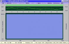
To what extent the bins are filled with data can be checked by selecting the Histogram (in the lower window). The first picture shows the histogram obtained with 4.001kHz, all bins are filled, which is okay.
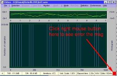
The second picture is obtained with 4.000kHz, that is not okay, as the bins are sparsely filled. Also note the small square in the lower left corner. The red color signals an error condition. Click on it to see the error msg, in this case: "Too many gaps", i.e. too many bins with no data, which ultimately leads to an ill defined residual. BTW, depending on the sparsity and distribution, this is not always catastrophic.
Cheers, E.
Attachments
Calibration
As for the DAC, 0.707 is correct, being the reciprocal value of 1.414. This is also explained in post #55. Nevertheless, I see it leads to confusion. So should I change the program, so that for the ADC as well as ADC the same calibration factor can be used? Please vote on this matter everyone who uses DiAna.
Cheers, E.
It does work with my RTX, no error messages.
I'm still confused about the calibration though. I choose 0dBV out and 0dBV in at the RTX, and my DMM has confirmed that at this setting 0dBFS equals 1Vrms, so I set "Calibration ADC-1/2" to 1.414 (as shown in the screen capture).
However, under this setting, I'll have to set "Output level (Vp)" under Preference->Distortion to be less than 0.707, or else the input becomes over range and end up with very high distortion.
As for the DAC, 0.707 is correct, being the reciprocal value of 1.414. This is also explained in post #55. Nevertheless, I see it leads to confusion. So should I change the program, so that for the ADC as well as ADC the same calibration factor can be used? Please vote on this matter everyone who uses DiAna.
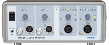
Assuming that this figure is indeed the full scale value, then set the ADC calibration to 1.414. If the I/O level on RTX is set to another value, needless to say that calibration factors in DiAna have to be adjusted accordingly.The exact full scale input and output voltages are conveniently displaced at the front panel.
I use 0dBV (1Vrms) output and 0dBV input for my test.
Cheers, E.
@Edmond thank you for your very thorough explanation. I completely understand now.
My brain has been wrapped around FFT, FHT and the inverse for about six months now and that's where my thinking is.
This is much more like an analog process done in binary. Much like Bob's distortion magnifier.
Cheers,
My brain has been wrapped around FFT, FHT and the inverse for about six months now and that's where my thinking is.
This is much more like an analog process done in binary. Much like Bob's distortion magnifier.
Cheers,
@David,
>"Much like Bob's distortion magnifier."
I Have only a vague idea how that works, but if you mean the suppression of the fundamental before doing the analysis, then, indeed, it is analogue to Bob's magnifier. This also explains why there is so little 'grass' (leakage) around the spectrum line at the fundamental. As a matter of fact, the FHT doesn't contain the fundamental, as it has already been highly suppressed at that stage, but later on the actual value is back-substituted.
How about your vote (see post 116) regarding DAC calibration?
Cheers, E.
Hi Edmond
making the DAC calibration value similar to ADC makes sense. In testing RTX , THD+ Noise value is not as I see in other software. But THD seems matching ?
I have not found any new issues
Still export of THD harmonic records will be preferable for users to appreciate any such application.
making the DAC calibration value similar to ADC makes sense. In testing RTX , THD+ Noise value is not as I see in other software. But THD seems matching ?
I have not found any new issues
Still export of THD harmonic records will be preferable for users to appreciate any such application.
As for the DAC, 0.707 is correct, being the reciprocal value of 1.414. This is also explained in post #55. Nevertheless, I see it leads to confusion. So should I change the program, so that for the ADC as well as ADC the same calibration factor can be used? Please vote on this matter everyone who uses DiAna.
...
I don't have any problem as is, because after your posts, I have understand the procedure.
But, what you mean with that I have underline done? Can you give us an example?
By the way, I tried the new DiAna version, and I have an error message at the startup of program "Failed to access info of driver nr 4. Error code: -3"
At the config file, there are the:
AsioDriverName=ASIO E-MU 0404 | USB
ASIOdriverNumber=4
If I press OK, then the program runs well.
- Home
- Design & Build
- Equipment & Tools
- DiAna, a software Distortion Analyzer